WHEN I upgraded my Solidworks 2004 drafting package to Solidworks 2006, I wanted to try out its new features. What better than to do this with a design of a balanced beam steam engine.
I had seen large and very large balanced beam steam engines in museums but most of the time they were stationary and did not work.
We have in one of the museums here in Western Springs, Auckland, New Zealand a very large balanced beam engine which operated water pumps to keep the water levels down in certain areas of Auckland.
As far as I can remember this engine has not worked for years.
However, many years ago a group of volunteer steam enthusiasts took on the task of restoring this huge machine and in April 2009 it operated under its own steam.
The volunteers were from the Auckland Steam Engine Society Incorporated of which I am a member.
Model balanced beam steam engines have been built in all forms shapes and sizes, and I thought maybe it would a challenge to design one from scratch.
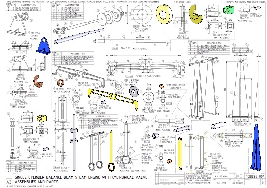
The result of my brainwave can be found and seen on the drawings 1CBBSE-000 to 1CBBSE-005
As you can see this engine has two balanced beams. One is operated by and connected to the piston and the other is connected to the valve.
I have tried to keep the design as simple as possible, however, and anyone who would like to built this little engine should have the basic hand tools, drill press and a lathe. A milling machine would be also very handy.
Where I speak of “press fit” it should be an interference fit (tolerances as + 0.1 and/or hole -0.1)
Where I speak of “size for size” it should be that the two components can slide in one another. Tolerances are ±0.01mm. In general where we have axles, rods, locking pins etc which are moving or sliding in bearings or bushings the tolerance are size for size.
On the drawings, the bill of materials has an “item no” column which is represented as a balloon with the item number.
Also shown in a box are two numbers. The first one is the assembly number and the second one is the description number e.g. 100-01
The materials which are shown on the drawings are only indicative, the builder is free to choose the materials which he or she has available or which one think which would suit better.
The painting of the model is also left up the builder, the color scheme shown on the drawings are indicative only.
I will mention in rough detail the components which are shown in the assemblies.
I will not explain in detail how make the components because it depends on the builder’s tools and machinery. Also each modeler has his or hers own method of making the components and materials available
Here we go let’s begin!
Assembly 100
The components are basically the two main balance beams and some bushes and spacers and a locking screw.
Most of the components can be made from mild steel however the bearing bushes should be made of bronze.
As shown on the drawing the bushes are a press fit in their holes.
The oil holes to be drilled after the bushes have been pressed into the beam.
Assembly 101
The components are the main connection rod, which connects to the main beam and the piston rod, and two press fitted bush bearings. Again the oil holes to be drilled after assembly.
Assembly 102
The components are the crank connection rods, which connect to the main beam and the crank, which have two press fitted bush bearings, and an axle which keeps the two crank connection rods apart.
The axle and the bush bearings in the main beam are size for size.
Assembly 103
The main component here is the cylinder block and the valve housing. Besides that we have the top and bottom cover plates and some sliding bushes and pressure plates.
As shown on the drawings the cylinder block and the valve housing is made out off one piece and made of mild steel.
However if the builder finds it easier to make it out of two pieces then the builder may have to devise a way to join the two together.
The holes in the back of the cylinder block (M4), are there to allow the port holes (3.3mm) to be drilled, and those holes (M4) will be closed off later on with screw plugs.
Similarly the holes in the front of the valve housing (M4), are there to allow the port holes (3.3mm) to be drilled, and those holes (M4), will be closed off later on with screw plugs.
In section A-A the port holes are shown.
The top and bottom covers are secured to the cylinder and valve housing using threaded rod M4 and M3.
The piston top and bottom guide and valve rod guides should be made of brass and the holes in which the piston and/or valve rod slide should size for size
The guide plates and the pressure plates have cavities to accommodate sealing material such as Teflon or nylon or a material which can withstand heat and pressure.
Item 2 (103-14) is also used to fix the cylinder to the base plate and so is item 7 (103-35)
Also fixed to the valve housing are all the components shown next to the cylinder block, which are the steam inlet and the steam outlet pipes.
Assembly 104
The main component here is the flywheel and attached to it is the valve eccentric.
As can be seen from the drawings the flywheel is made up out off several components.
The cranks are fixed to the flywheel hub axle using press fit pins.
The hub is fixed to the hub axle using grub screws. The hub and the hub axle, which are size for size, can rotate with respect to each other. This is done to enable the eccentric to rotate with respect to the cranks thus achieving the possibility to advance or retard the opening of the steam port by the valve.
The valve eccentrics are pinned down to the flywheel hub using press fit pins.
The crankpins (104-18) are made out off either silver steel or stainless steel and have to be a size for size fit with the bearings in the connection rod.
Assembly 105
There are two components only. There is the flywheel support and the bearing. The bearing to be press fit into the support and the bearing to be size for size with the flywheel axle.
Assembly 106 and Assembly 107
Refer to Assembly 103
Assembly 108
These components are associated with the piston assembly.
The piston rod is made out off either silver steel or stainless steel and has to have a size for size fit with the piston top and bottom guide.
Also the piston itself should have a size for size fit in the cylinder. The Teflon centre of the piston is to create thickness and also to give good sealing.
The yoke is attached to the main beam con rod using a press fit pin (108-46), however, the pin is size for size with the bearing bush in the main con rod.
Assembly 109
These components are associated with the valve assembly. The valve can be made out off one piece, or the builder can opt to make it out off several pieces. As shown it is made out off either silver steel or stainless steel and has to have a size for size fit with the valve chamber and with the valve top and bottom guide and valve chamber.
The yoke is attached to the valve yoke linkage (300-38) using a press fit pin (108-39), however the pin is size for size with the bearing bush in the valve yoke linkage.
Assembly 113
These components are associated with the valve balance beam which consists of the beam it self and some bushes and spacers.
Most of the components can be made from mild steel however the bearing bushes should be made of bronze.
As shown on the drawing the bushes are a press fit.
The oil holes to be drilled after the bushes have been pressed into the beam.
Assembly 114
This assembly is a mixture of Assemblies 103, 105, 115 and the base plate.
Assembly 115
The components are the two supports made out off mild steel plate and the pivot axle which is made from silver or stainless steel. The pivot axle must be size for size with bearing bushes.
Assembly 116
The main component is the eccentric housing, also a bronze bush and a locking screw. The shaft of the locking screw should size for size with associated bushes. Again the oil holes the to be drilled after the bushes have been pressed into their respective holes.
Component 300-38
This connecting rod has only one bush, which is a press fit and size for size with pin 109-44, and the oil hole to be drilled after assembly.
Pin 113-62 should be a press fit in the top hole of the rod.
Assembly 200
This assembly consists of Assembly 114 and the wooden base.
When we come to assembling the whole machine it is advisable to put a little bit of oil when axles and/or pins are placed into bearing bushes and in general were materials are sliding in one another.
I hope the drawings are clear enough, and if the builder has any questions and/or suggestions he can contact me through the website.
Happy modelling!