BERNAYS’ TWO CYLINDER STEAM ENGINE
By Julius de Waal

BERNAYS’ TWO CYLINDER STEAM ENGINE
By Julius de Waal

The unusual Bernays engine is one of those fascinating creations from the ‘Golden Age’ of steam in the second half of the 19th century. These model drawings have been prepared by Julius de Waal. The Bernays was shown at the Paris Universal Exposition of 1878, from which the following report was made by United States Commissioners there.
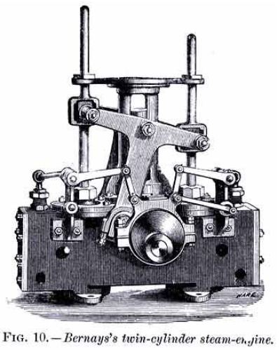
In the English department Mr. Joseph Bernays, of London, exhibited a twin-cylinder engine (Fig. 10), in which the crank is rotated by the intervention of a triangular connecting-rod an arrangement not new and long since apparently abandoned, but which this exhibitor makes practicable by an ingenious arrangement of eccentric and valve gear.
The two upright double-acting cylinders are placed with sufficient space between them to receive the crank-shaft. The pistons are connected to one crank by means of a triangular connecting rod, which causes them to move as if connected to two cranks at right angles to each other.
The steam distribution in the two cylinders is governed by one ordinary eccentric and its connections in a manner analogous to that by which the main crank governs the motion of the two pistons.
Two eyes are provided on the eccentric ring, carrying rods or levers, through which the valves are acted upon. The position of, and distance between, these eyes bear the same relation to the throw of the eccentric as the measurements of the main connecting-rod bear to the throw of the crank, reproducing on a smaller scale the triangular connection between the crank and the two piston-rods in the eccentric, and valve-rods, and the steam is correctly distributed. The eccentric is loose in the shaft and is thrown to the right or left for the purpose of reversing the engine. The position of the crank-shaft in relation to the cylinders may be varied in height to suit any required purpose.
In this engine there is no dead point, for the reason that both pistons can never be at the ends of their respective strokes at the same time, since they reach their limit of movement when the crank-pin passes a point in line closest to the pin of the triangle to which either engine-piston attaches.
Geometry can be derived from the Bernay’s Patent compound Engine drawings from the Feb 7, 1879 edition of “The Engineer”

Click on Julius’ drawings below to download - for personal use only.


