STEAM ENGINE
PISTON RINGS
By Artisan

STEAM ENGINE
PISTON RINGS
By Artisan
During a recent discussion with a fellow club member on the subject of piston sealing in steam engines it was suggested that details of the seals I employ in my models may be of interest to other people. There is already a good deal of information on the subject of piston rings for both steam and internal combustion engines in the model engineering literature and there is nothing revolutionary about my ideas, but I have nevertheless put together a few notes and pictures giving details of the design and manufacture of the piston rings I use in my locomotives in the hope that this may be of some general interest. This article has been updated since first being published on MEWS.
I always use bronze (or gunmetal) for cylinders to avoid the risk of corrosion in iron cylinders. The choice of sealing systems for pistons working in bronze or gunmetal cylinders is rather limited.
The use of traditional iron piston rings is not generally favoured in cylinders of non ferrous materials because of the risk of scoring the bores and corrosion of the rings. Another possibility is the use of piston rings made from bronze. This is a perfectly reasonable application but since both the rings and cylinder walls are of similar hardness there is still a potential for scoring of the bore.
In days gone by the usual practice was to machine a groove in the piston and pack it with graphite impregnated yarn of some sort. With the advent of O-rings some people have adopted these as a replacement for the yarn packing but personally I do not consider that the sliding motion between piston and cylinder is an appropriate use of O-ring seals. The arrival on the scene of low friction plastic materials with a capability of withstanding the temperatures reached in steam engine cylinders has led to the adoption of piston rings made from one or other forms of these plastics.

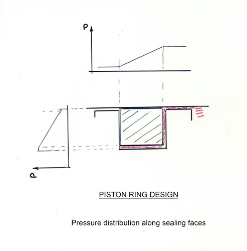
Figure 1
There are numerous mentions of this practice in the model engineering Press and virtually all of them propose the use of O-rings behind (i.e. inside) the plastic rings in order to press the ring onto the cylinder wall. In my opinion use of O-rings in this way is unnecessary if the piston rings are properly made and results in unnecessarily high contact pressure with accompanying
potential for wear and unnecessary resistance to motion.
Before discussing the design and manufacture of the rings let us consider the actual sealing mechanism. Figure 1illustrates the pressure distribution around a properly fitting piston ring. The pressure side and underside of the ring are exposed to the full cylinder pressure. The opposite side of the ring and the ring / cylinder interface will represent leak paths which, if the ring has been properly manufactured and fitted, will be very narrow and the leakage flow will be lamina. This will result in an almost linear pressure gradient along the leak path between the high and low pressure sides of the ring. This in turn results in a net sealing force against the cylinder wall and the downstream side of the groove. For this state of affairs to be established there must be a small initial interface force between the ring and cylinder wall and the ring must fit the bore accurately. If these conditions are satisfied the sealing functions will self energize as the pressure difference across the piston develops.
The basic design of the piston rings which I have incorporated in my last three locomotives is shown in Figure 2. The material which I use for my rings is a graphite loaded PTFE.

Figure 2 Basic design.
Virgin PTFE is too soft and has a very high coefficient of thermal expansion. The material I use was recommended to me by a supplier who I was in contact with when trying to obtain a material called Flouroscint, which is a mica loaded form of PTFE and has been used by a number of model engineers for piston rings.
The firm concerned said that they could not understand why model engineers persisted in using this material because it is very expensive and graphite loaded PTFE was not only cheaper but, in their opinion, more suitable for the duty! I therefore followed their advice and have used rings of 25% or 35% graphite loaded PTFE ever since.
The material still has a fairly high coefficient of expansion, so rather than have a large gap in the rings my design incorporates an overlapping joint. Traditional cast iron rings are expanded to provide the initial sealing pressure on the cylinder walls by peening the inside of the ring or by some form of heat treatment.
These options are not available for plastic rings and the initial wall loading must be achieved by making the ring oversize and compressing it to fit the cylinder after cutting to form a gap.This compression alters the shape of the ring so that it will no longer be truly circular. It will not be an accurate fit in the cylinder bore unless it is finish machined in the compressed state. This is essential to ensure the initial seal to enable the ring to ‘work’ properly.

Figure 3 Manufacturing details. (corrected 29 June 2017)


Once the joint in the ring has been machined it is compressed to the operational configuration and machined to finished size as illustrated by Figure 6 and photos 3 and 4.


Photo 5 below shows a simple tool for holding a finished machined ring to enable the sides to be dressed on 800 grit abrasive paper spread on a surface plate to ensure a good finish for sealing and, if necessary, adjusting the width of the ring to suit the piston groove. This fit must be close but allow free movement of the ring in the groove at working temperature.

