Admiral Sir Reginald Bacon’s
15” HOWITZER
IN 1:12 SCALE

Admiral Sir Reginald Bacon’s
15” HOWITZER
IN 1:12 SCALE


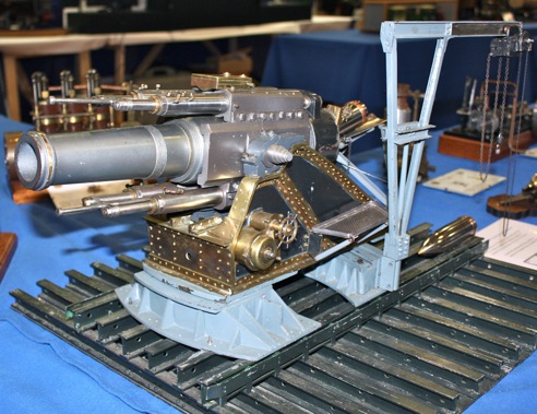
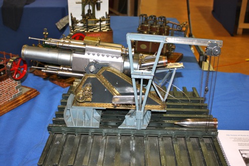
The full size weapon was designed under his direction at a time when he was managing director of Coventry Ordnance Works. It was a response to a perceived need for a heavier weapon following a successful German attack on the Liege forts. At the time the largest Howitzer available to the British forces was 9.2" calibre. The design brief was for a weapon that could be moved rapidly and capable of being mounted and dismounted by man power and 125hp tractors for transport.
The design incorporated some ingenious design features:


For details of how it worked some pictures available on the internet and a short film clip also from the internet were used to work out the way the gun was operated. It required the production of a new capstan for the elevation mechanism and a smaller one for the Breech lock. Details for these items were based on the pictures. The loading tray and crane had been badly twisted and at some time in the past they had been covered in a thick grey paint.
The principle of the loading system was surmised to be: the barrel was depressed to the horizontal; the breech is unlocked and swung clear; the loading tray was swung down to rest on the interrupted threads the breech locks into, a brass pad under the tray was discovered and presumed for this purpose; a round was picked up in a cradle by the crane and swung over the tray before being lowered into position; the projectile, weighing almost half a ton, was then rammed into the breech by a team of gunners hauling a wire rope and chain combination rigged to force it into the breech. This conjecture is supported by the pictures. The gunners operating the gun used side mounted platforms to reach the breech etc. These had been badly damaged over the years but have now been repaired and replaced.

To complete the work on the model various sizes chain were sourced to scale for the loading crane, and the chain hoist repaired. New legs were made for the tray in order for it to sit correctly for loading and new chains were made to limit its swing when not in use. As many of the original fastenings as possible were reused, with modem machine made items being used where the originals were missing or beyond use. The thick paint was removed and the items sprayed with a paint specially mixed for the job. Unfortunately, the firing mechanism is missing from the breech. As there is no design information available no attempt has been made to replace it. The platform has been repaired as necessary then cleaned.

MEWS IS SPONSORED BY - CHRONOS - PAULTHECAD.CO.UK - ECCENTRIC ENGINEERING - WARCO - BRISTOL EXHIBITION - HARROGATE EXHIBITION - MERIDIENNE EXHIBITIONS - LYNX MODELS - CAMDEN MINIATURE STEAM - TRANSWAVE CONVERTERS - MESSE SINSHEIM -
Editor - David Carpenter