This project started for me in early 2022 as a result of enquiries about how the club (Bristol) had made the Brunel loco. One such enquiry from Tim Coles was “how did you make front nose”. While answering this question in a series of e-mail exchanges, I was gradually and willingly drawn into offering to create the CAD model of the cab for the 18,100 loco that Tim and his team were endeavouring to finish off, a large part of which had already been completed by the previous owner but who was no longer able to carry on.
The original cab construction was intended to be a thin sheet covering over a complex water jet cut framework.

I then further offered to make the cab - unfortunately for me there’s a cab at each end! My offerings for the cab construction were either a plastic 2D printed one (as our club loco, Brunel) or, by trying something conventional but new to me, made in glass fibre, laid up on a 3D printed mould. This was a method I had little confidence in achieving,
However, I wanted to make the cab an improvement over the one I had made for Brunel in terms of resistance to potential ‘wilting’ on hot days and strong sunshine. The cab I made this time used a different technique, being cast in resin from 3D printed moulds to produce a 5mm thick hollow shell.
Here are the steps to completion:

-
•First, create a 3D model of the cab using Fusion 360 - easy to say but getting the shapes right and lofting all the curves involved a lot of trial and error and took a long time!
-
•Divide the cab into as few printable parts as possible (two) and 3D print as a hollow shell, assemble and fill, then sand the exterior smooth. Spray with release agent.

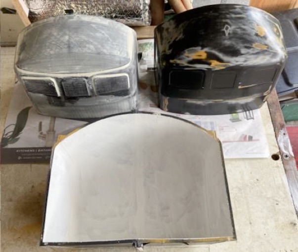
Printed Cab top right , Former suspended inside
Former top left, Female Mould cavity, and silicone rubber
Female mould, bottom


-
•Suspend the 3D printed cab inside the female mould, creating a 5mm thick cavity around the cab.
-
•Pour silicone rubber into the 5mm cavity (and allow to fully set before taking apart!)
-
•


-
•Above, releasing the Printed Cab from silicone mould.
-
•Remove the printed cab by splitting the mould case and stretch the silicone rubber off the 3D printed cab – reassemble the mould and silicone liner and you now have a detailed female impression of the cab in silicone rubber – something that will not stick to anything so should make removing the cast cab straightforward and allow casting of multiple cabs.


-
•Design a Former that is 5 mm smaller all round than the external profile of the cab, essentially a part that looks like a smaller cab. This will enable a 5mm thick hollow shell version of the cab to be cast rather than a big solid lump – resin isn’t cheap!
-
•Print the Former, (two parts) assemble and ensure its leak proof. Spray with release agent
-
•Suspend the Former inside the female mould to create a 5mm thick cavity.


-
•Pour Castable Resin* into the cavity and allow to set – work quickly but carefully so as to finish pouring within the 15 min gel time. Sounds a long time but goes quickly!
*Polycraft SG2000 castable resin
-
•Split the female mould to release the resin cab which is a detailed and accurate copy of the 3D printed one (with the Former well and truly stuck inside!).

-
•Sacrificial removal of Former. Use a hot air gun to soften the Former (around 70 degrees) and extract it from the shell of the resin cab.
-
•
-
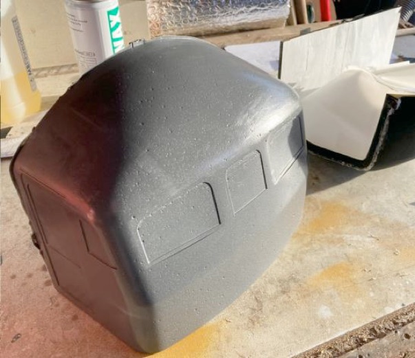
•Stand back and feel grateful all that effort produced something useful to work with – except for having a surface like the moon!
-
•Fill all those craters with a fine car epoxy filler, sand back, and check for missed craters.
-
•Repeat step until it looks perfect, Window frames in background.

-
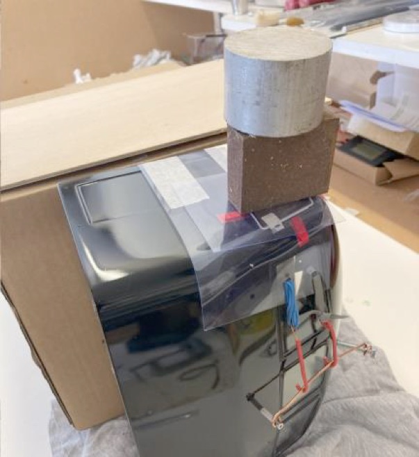
•When it reaches an acceptable standard take your courage in your right hand and spray the two final gloss black coats of paint, shutting your mind to the potential for runs, orange peel, and flies taking a liking to the smell.
-
•Make and add Perspex windows, 3D printed window frames, wipers, top light, door handles, door grab rails, three magnetic feet to the base of the cab, two location lugs to base, aluminium rear bulkhead plus support angle. The most difficult tricky part of this stage was making the two corner windows which are curved.
I’ve never mastered the apparently simple skill of heating Perspex to a suitable temperature for vacuum forming without getting micro bubbles. I must have had twelve or more attempts, each one consuming a lot more than the size of the window (to allow for clamping down), before forming a pair that looked acceptable.

I was lucky to have the help of Kevin Slater who kindly water jet cut the other (flat) windows to size for me, thereby avoiding a lot of time spent fret sawing them from sheet. He did cut the curved windows but I found it impossible to form them successfully when cut to size. I pictured doing this by “drape” forming - it looked easy on U-Tube!

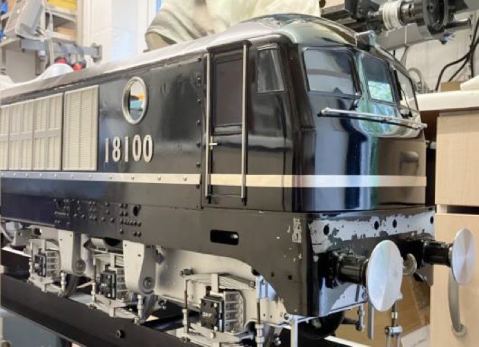
It all began in February 2022 and the first cab was finally finished and sent to Tim just before the Midland ME Exhibition, October 23, where the complete loco model was exhibited (as shown at top of page). It fitted on to the chassis OK and all that remains now is make cab No.2 – now how did I make that wiper? ……I’m sure I made eight of those so where did I put them?…….


