BUILDING WILDING’S EIGHT DAY WALL CLOCK
Jim Jennings

BUILDING WILDING’S EIGHT DAY WALL CLOCK
Jim Jennings
I discovered that John Wilding had designed such a time-piece, and had put all the instructions for construction into book form. After purchasing said book at great expense (then £7.25), I read it and decided that construction would be within my limited capabilities, although I would have to adapt my lathe so that I would be able to cut gear wheels. I would also need to learn a new vocabulary, as clock-makers used terms which were foreign to me.

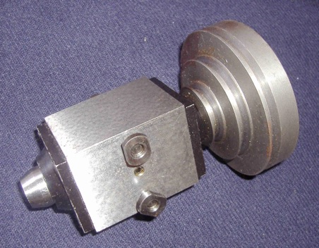
A simple cutting frame was necessary which held cutters made from silver steel for cutting the (gear) wheels, and was designed to rotate at about 4,000 rpm. It was driven by a pulley and belt from my pistol drill arranged behind the lathe bed. This was superseded by a (purchased) milling spindle which was mounted on the vertical slide and driven by an external electric motor. See photograph.
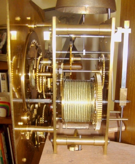
The other item was a depthing tool which I have either lost or given away. This is used to plant the wheels and pinions at the correct distance apart to ensure smooth running of the clock.
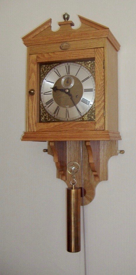
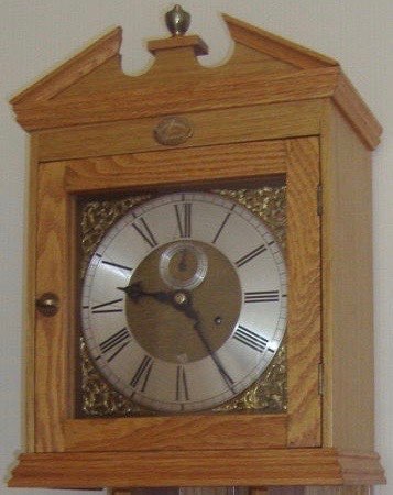
These two items were the main additions I had to make in order to begin construction; learning the new vocabulary came about gradually as I worked my way through the book. A few of the terms are: pinion (small gear wheel with up to 20 teeth); pitch circle, diametral pitch, addendum (terms used to describe {gear} wheels); leaf (individual tooth of a pinion); spandrel (not to be confused with Spangles, which were square, fruit-flavoured sweets, traditionally sucked while watching films in the cinema, but decorative brass castings at each corner of the dial); chapter ring (the broad ring of metal on the dial on which are engraved the numerals), and cartouche (the engraved
plate on the dial which shows the maker’s name).
I think the above gives an indication of the learning curve I had to negotiate when I changed jobs from locomotive engineer to horologist – but if I could do it, I’m sure anyone else could do likewise.