The Allchin Royal Chester traction engine has been popular with model engineers for 60 years when a model in 1:8 scale was described in Model Engineer magazine by Bill Hughes. This was the first time that instructions were given on how to build a true-scale live steam working traction engine.
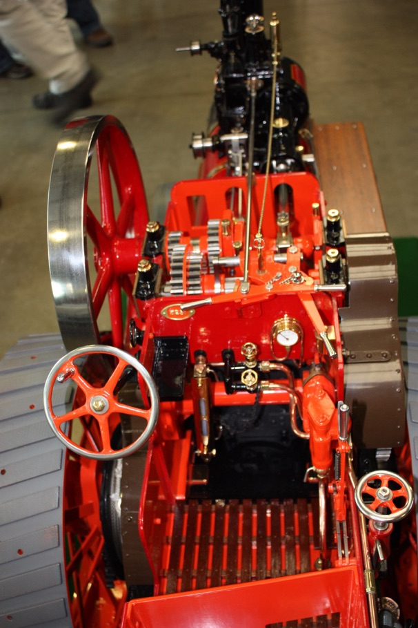
The design has been adapted to larger and smaller scales by model engineers. The fine Allchin illustrated here is a 1:4 scale Allchin shown by John Alan Cooke at a National Model Engineering and Modelling Exhibition.
John built the engine using a Myford ML7 and a Dore Westbury milling machine built specially for this project. The front wheels, flywheel, spud pan, and differential centre were machined with the aid of a Rodney Big Turn. Rear wheels were turned on a friend’s large lathe.
Inspiration for Hughes’ masterpiece was the last traction engine made by Allchins of Northampton in 1925. It was tentatively given the name Royal Chester as it was intended to show the engine at the Royal Show in Chester. Although she was never fitted with name plates, the name stuck.
No 3251 was a 7hp general purpose engine which Bill Hughes first saw in 1948 while out ‘hunting’ engines on foot and bicycle in North-east Derbyshire. She was in the yard of J.G. and B. Earnshaw, threshing contractors, along with two other Allchins and a Marshall. The Earnshaw brothers allowed him to pay many visits to measure the engine. The other three engines were sold for £25 a piece (what would they be worth today?) but Bill persuaded pioneer preservationist, Chris Lambert, to buy the Allchin engine and it was restored.
Bill’s articles proved highly popular and large numbers of models were built, mostly to the scale of his design, but some others ranging from 15mm/ft to half size. He updated the articles in the 1970s and a book was also produced.
Dimensions recorded by Bill Hughes:
-
•Rear Wheels: 6 ft. diameter, 8.5in. wide, two driving-pins.
-
•Front Wheels: 3 ft 10in 9 in. wide 10 spokes.
-
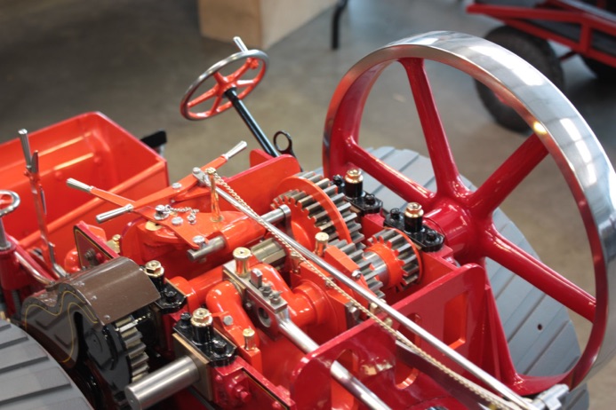
•Flywheel: 4 ft. 6 in. diameter, rim 6 in. wide by 1.75 in. thick, 6 spokes.
-
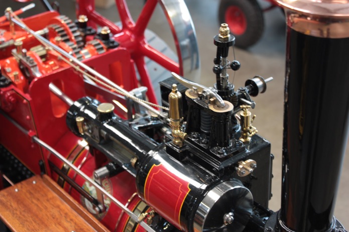
•Single Cylinder: 10 in. bore by 12 in. stroke.
-
•Connecting-rod centres: 3 ft. 3 in.
-
•Eccentric-rod centres: 2 ft. 8.5in. Eccentric-sheave diameter: 7 in.
-
•Crankshaft as forged: 4 in. diameter. (All journals turned to 3.5in. diameter.)
-
•Steering-wheel: 17 in. diameter, 5 spokes.
-
•Brake operating wheel: 13 in. diameter, 6 spokes.
-
•Hornplates 0.625 in. thick, and distance between them is 32.5 In. thus firebox is also 32.5 in. wide and boiler ditto diameter, with lagging 1.5in thick.
-
•Bolting flange at chimney foot 13 in. diameter.
-
•Width of engine over hind wheels: 7 ft. 7 in.
-
•Width over tender: 2 ft. 10.5 in.
-
•Thickness of plating of tender: 0.75 in.
-
•Distance between tender side and nearside hind wheel: 13 in.
-
•Distance between tender side and offside hind wheel: 10.5in.
-
•Steering on nearside. Pump in cab, at offside, driven by eccentric between crank and crankshaft bearing.