3L BENTLEY CYLINDER BLOCK FABRICATION
Part 2/2 by Mike Sayers

3L BENTLEY CYLINDER BLOCK FABRICATION
Part 2/2 by Mike Sayers


First phase of silver soldering after cleaning and bead blasting followed advice given by Keith Hales, well-known from CuP Alloys, was that silver soldering should be performed in stages. Silver solder flux will only stay active at its high temperature for a certain length of time. Especially with cast iron, the flux needs to be at its most aggressive so at each stage the work was cleaned, degreased and refluxed.

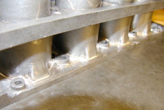
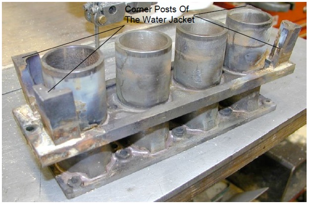
At each stage of the operation the cleaned and fluxed assemblies were preheated on an old domestic electric hotplate . The job was left heating until the whole was at as near an even heat throughout, checking with a digital thermocouple. The max temperature that could be achieved on the hot plate reached the point at which the T5 flux just began to become transparent. It did not take a great deal of heat from an oxy-acetylene flame to reach the point where the 55% silver solder flashed round and penetrated all the joints.
In the photo the combustion head is being attached to the barrels and water jacket.
The components were then heated up on the hot plate. The weight seen in the photo held the various parts together during heating.
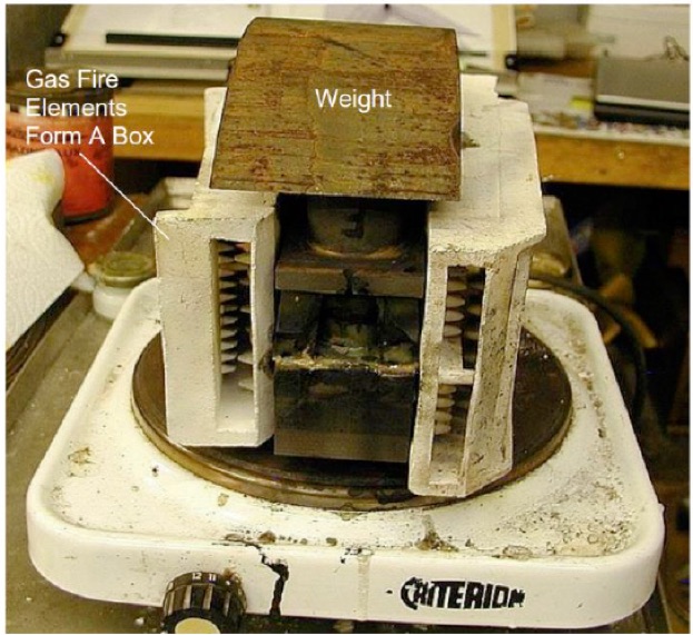
The components were then left for well over an hour in order for the heat to soak all the way through them. The parts were heated just to the point where the flux turns transparent. An oxy-acetylene torch was used to go around all the joints feeding in the silver solder. It didn’t take a lot of external heat to get the solder to flow.
To use the minimum temperature Keith Hales recommended a 55% silver solder which is fairly flexible when set. The whole system worked very well.
After each stage of silver soldering, a heat proof blanket was placed over the heater and contents, with some gas fire elements helping to ‘box’ the component. After every half an hour, the thermostat was turned down a notch, so that the cooling was gentle and gradual. It took most of the day to cool down so the component could be handled and worked on again.
Below is the final stage, after the cylinder head and corner posts have been silver soldered on. It is now ready for cleaning and bead blasting. The piece used for the weight is a piece of cast iron used to make the other components.
It was beautiful metal to machine, and being continuous the carbon is held. It silver soldered really well. The 4.5 litre block was manufactured from the rest of the bar.

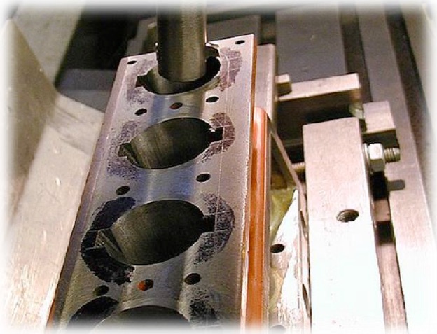
The machine bed is tilted at 5° top side out. A sine bar was not necessary for this operation. The table was set using division scales underneath the table.
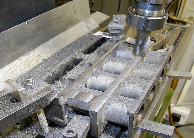
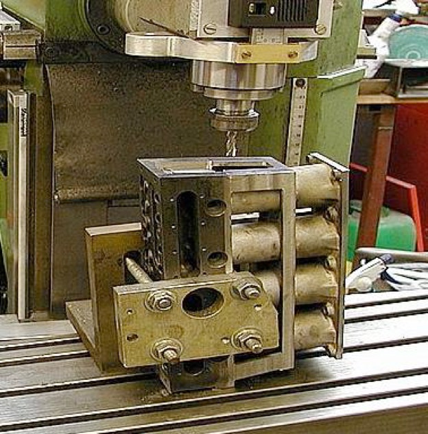
This operation demonstrates why the triangles were left on the liners when machining operations began, otherwise the inside might meet the outside!
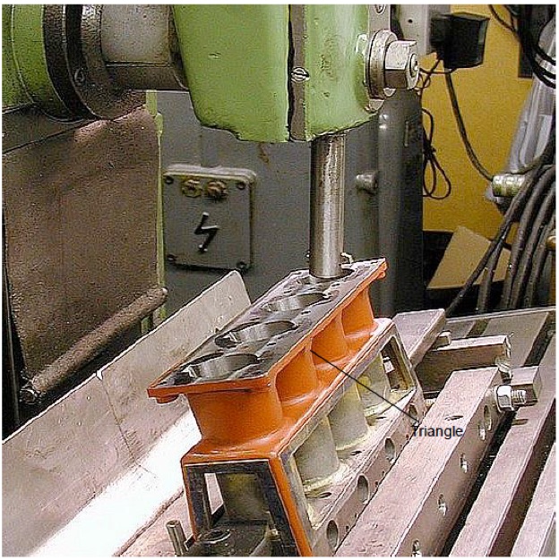
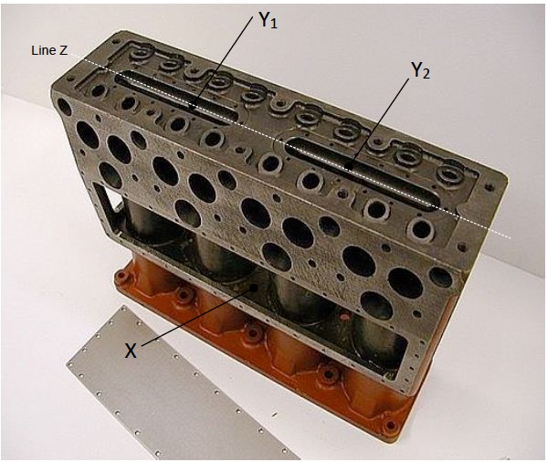
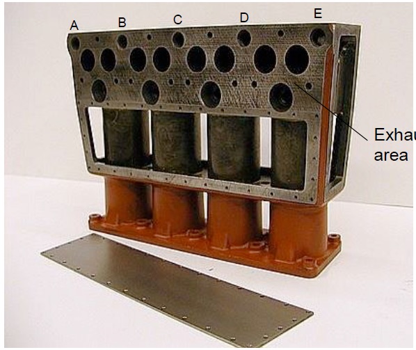
Here is the finished cylinder block with all the detailing in the top and all the screwed holes present. There are 148 10BA tapped holes in total. There are six water plates, two in the top, two in the sides and two in the ends. There are 32 tapped holes in the side water plates on each side, 14 in each of the two plates on the top and 28 in each of the two ends. No 10BA taps were broken in the operation. Honest!
When making a water-cooled engine, and fabricating it like this, one problem is getting the water to flow through the cylinder head, because all the internal coring is impossible to machine.
The cold water flows back from the radiator into area X in the previous photo.
It was impossible to reproduce all the complicated internal coring as in the original castings. The only thing to do was drill up from area X into the two water spaces at Y. The ends were connected by a hole drilled along line Z and through the two water spaces Y1 and Y2.
This allowed the water to come right through the block, and out through the holes A-E into the water rail on the outside. It was the best that could be done, and has been reasonably successful. There is enough water going through the head to cool it, and it never got too hot running at exhibitions.
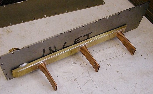
The full-size water plates were 3mm thick aluminium plates, so for 1:3 scale they had to be 1mm thick. The plates had to be decent quality aluminium and very stiff. Obtaining high quality hard tempered aluminium that would stay flat and not bend and scratch is difficult. Also sourcing the small quantity required was virtually impossible.
What was available was some 1mm sheet titanium that had been on the shelf for twenty years from a previous project. That is what the water plates were made from. The sheet is very rigid and doesn’t scratch but is hard to cut. However, it does machine well if the tools are sharp. The titanium sheet was also used for the 4.5 Litre scale Bentley engine.
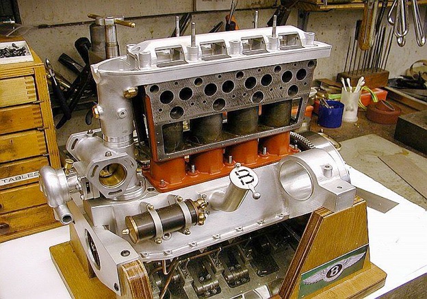
There was a concern, because the vertical drive in the front ‘turret’ connecting the crankcase to the camshaft, had to be absolutely in line when assembling the various components from top to bottom. Fortunately, the small clearances around the top and bottom bolt holes allowed the vertical drive to centralize correctly.






Modelengineeringwebsite.com
the only free and the only weekly magazine for model engineers.
Editor: David Carpenter