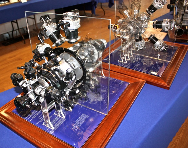
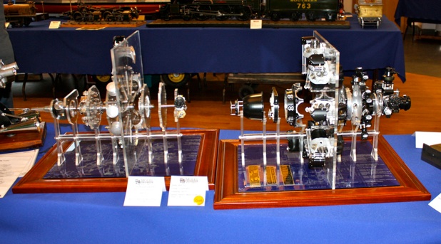
A 1:4 scale model of a single-row, nine-cylinder, air-cooled, poppet-valve, supercharged aero-engine.
The Mercury series of aero-engines evolved from and are direct descendants of Roy Feddon’s other masterpiece, the Bristol Jupiter.
Design work started in 1926 for a small diameter, high-speed supercharged racing engine for the 1926 Schneider Trophy Contest. It developed over 900HP when fitted in the Short-Bristow Crusader floatplane. This venture was not a success.
From 1935 onwards, the Mercury Mk V111, because of it’s smaller diameter, became a popular engine for fighter and high-speed bomber aircraft. Notable aircraft types being:
the Gloucester Gladiator, the last biplane fighter for the RAF, the Westland Lysander light army co-operation and spotter aircraft and
the Bristol Blenheim and Bolingbroke light bombers.
The Mercury MK V111 produced 852 HP to a rated altitude of 13,000 ft, at +5 lb./sq. inch of boost and a maximum engine speed of 2,650 RPM. It ran on 87 octane petrol. The propeller was driven at slower speed via a 2:1 epicyclic reduction gearbox.
The 24.9 litre Mercury and it’s bigger brother the 28.7 litre Pegasus were the last of a long line of Bristol designed poppet valve engines. They were eventually superseded by a completely new series of Bristol sleeve valve engines.
The Model
This display is created from one of my two 1:4 scale models of the Bristol Mercury Mk V111s. The exploded display was inspired by a similar display exhibited in Deutsche Technik Museum in Berlin.
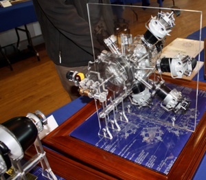
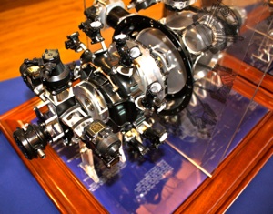
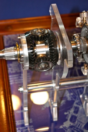
The first display unit shows the layout and operation of the numerous internal mechanisms that together constitute a Bristol Mercury nine-cylinder radial engine. Each mechanism is functional and will rotate by hand.
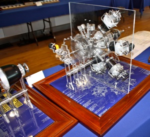
The second display unit, which is static, shows the outer casings and the cylinders of the same engine. All the casings, with the exception of the inlet manifolds are machined from solid billets of aluminium alloy. Most (80%) of the billets disappeared as swarf.
Component Sections
Propeller shaft. Either a wooden two blade or a variable pitch 3 bladed propeller were fitted.
Epicyclic speed reduction gearbox. The propeller rotates at half of the engine speed.
Cam gear and tappet assembly. The cam drum rotates at 1/8 engine speed. The front cam ring drives the exhaust valves and the rear cam ring drives the inlet valves.
Crank shaft assembly. Comprises a master rod and eight slave (Articulated) connecting rods. The master rod is positioned in one of the lower cylinders which are always more oily than the rest.
Dry sump. This collects the used lubrication oil mist. It condenses the oil mist and separates the unwanted air. The used oil is then returned to the main oil tank by the scavenge pump.
Cylinders. The aluminium cylinder heads are shrunk and screwed to the steel cylinders. The cylinder head contains four valves per cylinder which are operated by a ‘floating’ rocker assembly via push rods. There are a total of 36 valves in each engine. The ‘floating’ rocker assembly compensated for cylinder expansion.
Supercharger and drive. The centrifugal supercharger impeller is driven by the epicyclic speed-up gearbox and rotates at about eight times engine speed. The supercharger is used to maintain a constant boost pressure from ground level to the rated altitude of 13,000 feet. The output of the supercharger is distributed to the cylinders via external pipe work, which helps cool the charge.
Accessory gearbox. This is a complex unit mounted on the rear of the engine, it drives all of the engine accessories and oil pumps. These include:
A Oil pressure pump
B Oil scavenge pump
C Oil filtration system
D Dual magneto ignition system
E Engine starter: gas, electric or inertia.
F Interrupter gear to synchronize the guns and propeller
G Electrical generator
Construction
The drawings were prepared from original Bristol engine blueprints. I decided to build two engines simultaneously. Construction has occupied most of the past twelve years. The second engine is intended to run.
This model is manufactured mostly from billet materials. The process is quite simple; start with a big expensive billet of material, machine 80% of the billet into swarf and with luck an engine part will slowly emerge.
Most of the machining was carried out on a home made (much modified) CNC mill and lathe based on EMCO machines. Both of these machines were once the property of HM Prison Service, where they were used to rehabilitate the offenders.
The only castings used are for the cylinder and supercharger inlet manifolds, they were manufactured by the lost wax process. There are 27 manifold casting on each engine.
Most of the gears used are commercial gears, extensively modified. Commercial gears were used as this was considered to be more economical than the purchase of such a large number of different involute gear cutter sizes.

