MY CORLISS
ENGINE BUILD
Part two by Vince Cutajar

MY CORLISS
ENGINE BUILD
Part two by Vince Cutajar
I finished the remaining two holes in the subplate. Then mounted the rotary table on the mill and clocked it in. Reset the DRO X and Y to 0. Mounted the subplate to the rotary table and dialed it in.
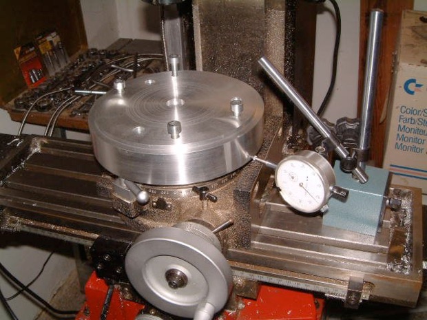
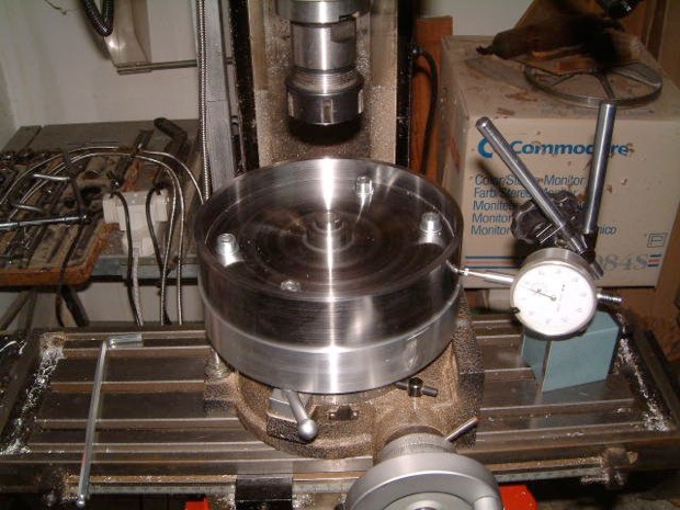
Fixed the flywheel to the subplate and checked that it was dialled in with the registers.
I then used an Excel sheet from to mark the outline of the spokes by using a cutter diameter of zero in the Excel sheet and a black permanent marker in the collet chuck.
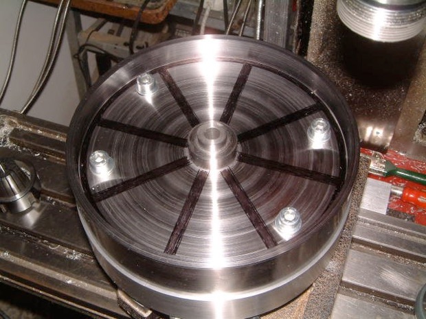
Seeing the spokes marked also helped me to decide which cutter diameter to use. I decided on a 6mm slot drill. Also, I decided to increase slightly the inner rim (where the spokes meet the outer rim).
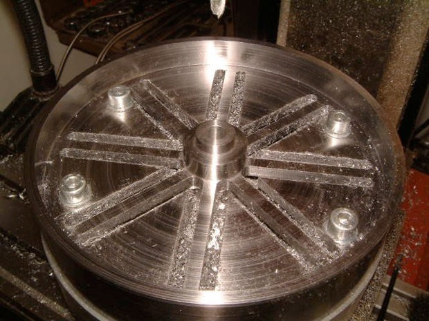
I milled the first slot using a 6mm slot drill but was having problems with plunging the slot drill. So instead I drilled a 5.5mm hole and did the plunging (0.5mm increments) in the hole.
Finished off the sides of the spokes and cleaned them up. Also cleaned up the hub side of the spokes.

I marked with a permanent marker 90 divisions (3mm wide) on the rim of the flywheel for the barring gear.

This helped me imagine better how it would look and made a decision to use a 3mm slot drill and mill the slots on the outside of the rim. The slots are 2mm long and 2mm deep.


To remove the flywheel segments I first chain drilled the arc and removed the segment by hand.

I then cleaned up the arc using a 6mm end mill.

When I started removing the segments which had the fixing bolts, I used additional clamping. I used a 10mm threaded rod through the hub and bolted the hub down. Before fitting the rotary table to the mill, I had fitted a special nut I had made on another project to the bottom of the rotary table. This allows me to bolt parts to the rotary table through the centre bore and still be able to turn the table.
As an added precaution I added another clamp to the rim.


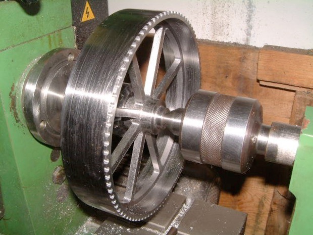
Then the clean-up. The plan was for it to be primed and painted at some point but I wanted to leave the outside and the sides of the rim bare metal. So I set it up in the lathe to try and remove, as much as possible, the machining marks in these areas with emery cloth.
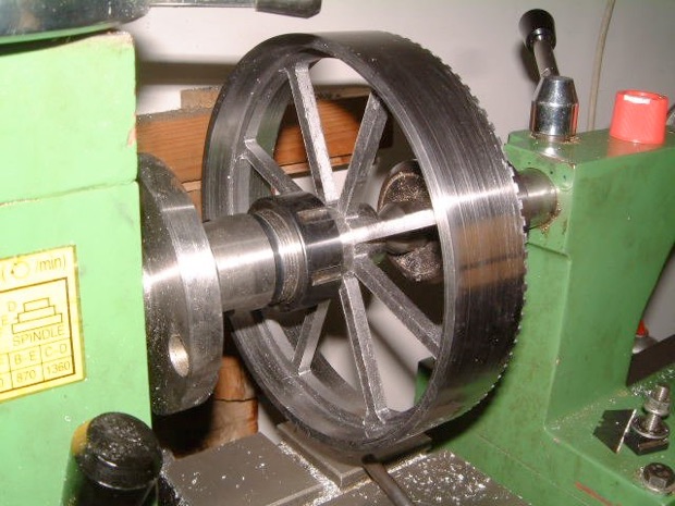
I sprayed it with a filler/primer. It worked out really well.


Modelengineeringwebsite.com
the only free and the only weekly magazine for model engineers.
Editor: David Carpenter


