ELECTRONIC LEADSCREW CONVERSION
Part one by Geoff Rogers

ELECTRONIC LEADSCREW CONVERSION
Part one by Geoff Rogers


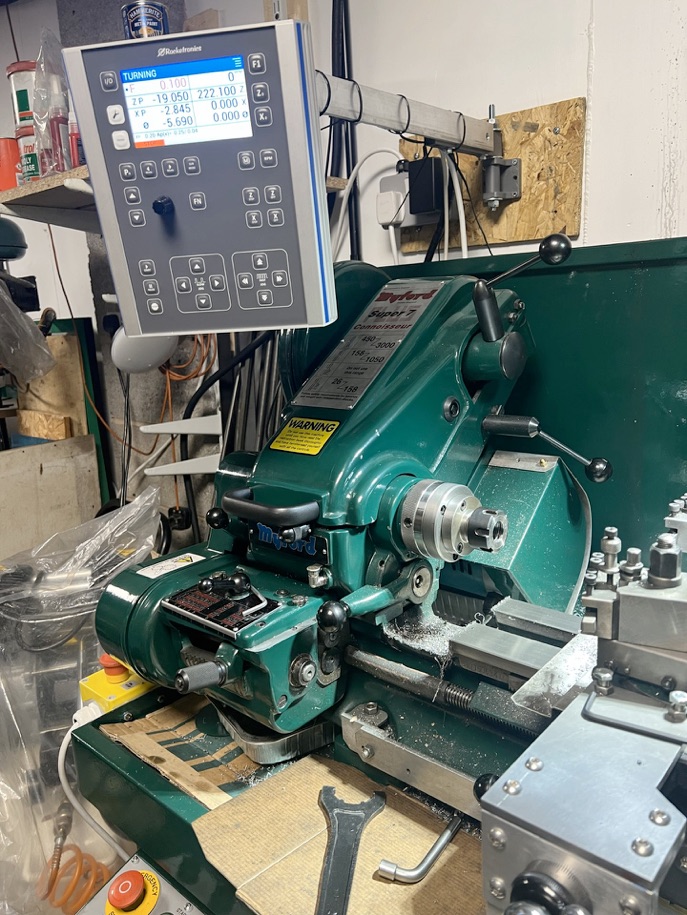
This is a useful electronic leadscrew adaptation as applied to the Myford Super 7 lathe.
What is an electronic leadscrew (ELS)?
What is the point?
Is it difficult to install?
Is it difficult to use?
What is an electronic leadscrew?
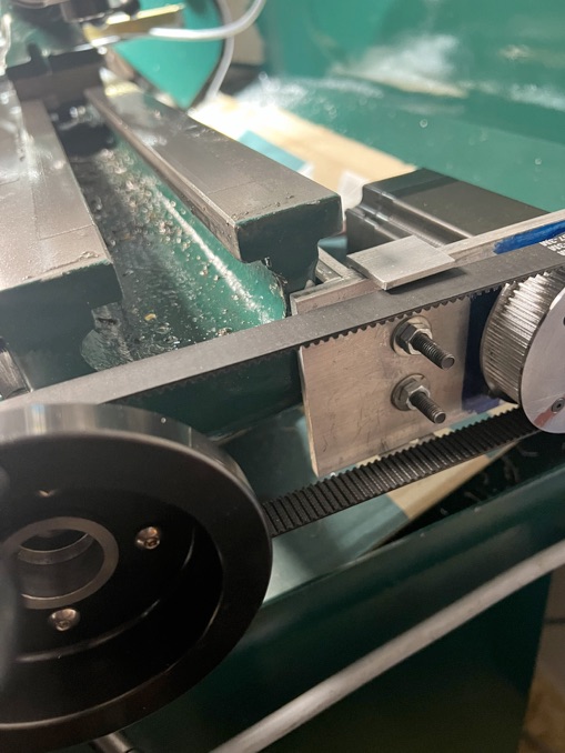
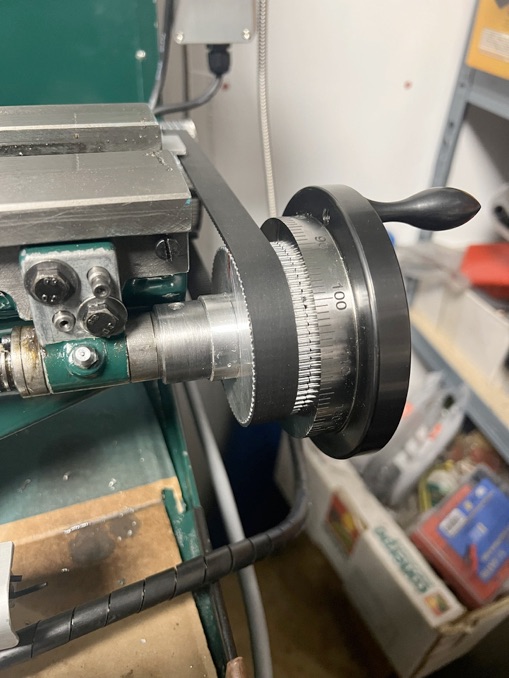
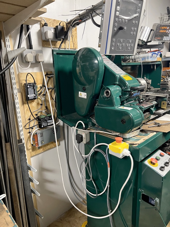
An electronic leadscrew is basically a drive system using stepper motors, that replaces the spindle driven gear arrangement at the headstock end used to drive the leadscrew. The stepper motors move the saddle (via the leadscrew) and cross slide as required by the controller unit, depending on the turning option selected.
For this exercise I selected a package from a German company called Rocketronics. I came across this company on the Model Engineer CNC forums page, where it was mentioned several times.
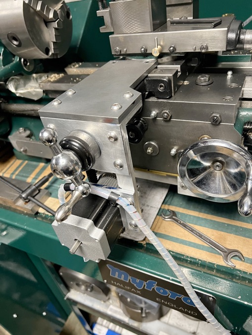
The package chosen provides for stepper motors for the leadscrew and cross-slide. There are some versions where only the leadscrew is stepper motor driven, but providing the cross-slide with a stepper motor significantly increases the versatility of the package as a whole.
The ELS comes as a package, consisting of:
•two stepper motors plus power supply and controllers,
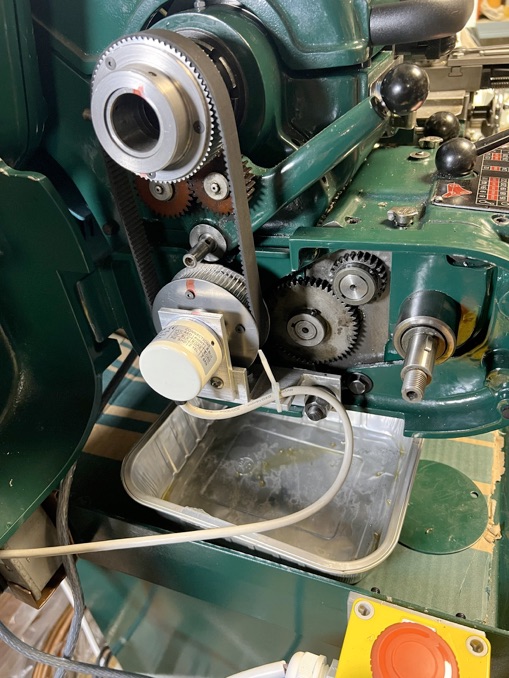
•a rotary encoder for the lathe spindle
•a controller (ELS 4Pro) that tells the stepper motors what to do and when.
•Some of the cabling required to for connecting if all together
•Wiring diagrams and a very useful manual.
They do not supply the parts required to fit the stepper motors or encoder to the lathe.
Rocketonics sell various packages, depending on the weight of the lathe. The Myford is at the smaller end of their range at 150kg.
This ELS package was fitted to the lathe with only small modifications being made and can be readily removed to restore the lathe back to original condition. The modifications made consist of small flats for the seating of grub screws, a clearance cut-out in the gearbox cover plus a bolt hole for the spindle encoder.
What is the point?
The main reasons for my looking at installing an ELS were to making screw cutting (metric and imperial) and taper turning easier.
The controller enables threads of any pitch (from 0.001mm to 16mm) to be readily machined. Parallel and taper threads can be produced.
Taper turning, both internal and external, is possible and is not limited by either top-slide or taper turning attachment travel. More on this later.
The controller has a good range of options:
•Gearbox Left - Electronic gear Left
•Gearbox Right- Electronic gear Right
•Turning - External long turning
•Boring- Internal long turning
•Facing
•Parting
•Undercut
•External thread - Straight or tapered thread External
•Internal thread - Straight or tapered thread Internal
•Thread <0 - External thread Never exceeding 0
•External taper
•Internal Taper
•Convex outer radius
•Concave outer radius
•Convex inner radius
•Concave inner radius
•Groove - Round or elliptical grooves
•Straight Groove
•Grinding- Grinding and pushing with spindle angle stationary or rotating -
•Drilling - Drilling cycle
•Angle measurement on chuck