BUILDING
ENGINE CARTS
Part 4 by Jason Ballamy


BUILDING
ENGINE CARTS
Part 4 by Jason Ballamy

Next the vertical engine cart. The design was based on photographs; this one this is gives an idea of the design of the wheels, rear axle and how the axle joins the channel frame.

The rear wheels are 152mm dia which can easily be cut from 6" ERW steel tube. For the fronts I also had some thicker walled 5 1/2" tube and by machining down the OD could get about 16mm difference in diameters. First job was to saw off a length a bit longer than needed for two rims and turn the 3mm and 5mm wall thicknesses down to give the 2mm thickness that I wanted. This is the smaller 5 1/2" tube having its OD reduced, I have left a section near the chuck full thickness to help keep the tube round as it starts to distort from the pressure from the chuck jaws if you are not careful. The larger rear wheels had the metal removed from the ID
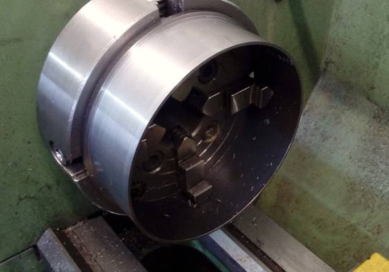
The ring can then be sawn in half and the two wheel rims machined back to the finished 3/4" width.

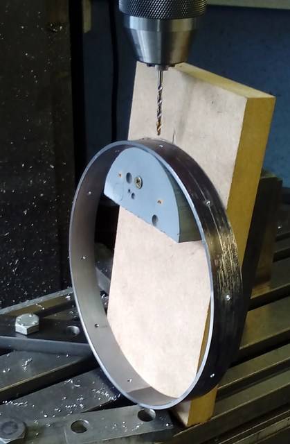
As the spokes are dished the holes need to be drilled at an angle, rather than faff about setting the rotary table at an angle I used it vertically to put 10 evenly spaced spot drilled dimples around the centre line and then made a simple jig to drill the holes at alternating angles, they then had a shallow CSK added.
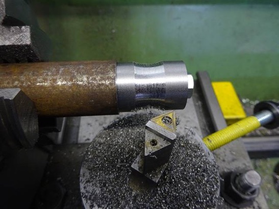
The hubs were machined to length and drilled through under size before mounting onto an arbor for some shaping using the ball turner.
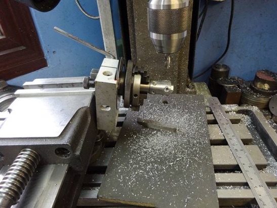
I dusted off my old Emco Unimat 3 dividing head/indexer as it had a 40T plate which made it easy to get the 10 holes and drilled, tapped and counter bored the hubs at an angle.
Finished hubs with some screws to give an idea of how the spokes should look
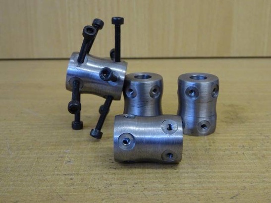
Talking of spokes if you thought three triples had a lot of similar parts then that’s nothing to wheel building, 40 spokes threaded one end and reduced in dia the other not much change out of a 3m length of 3mm round mild steel plus 40 bosses drilled and rounded on one end.
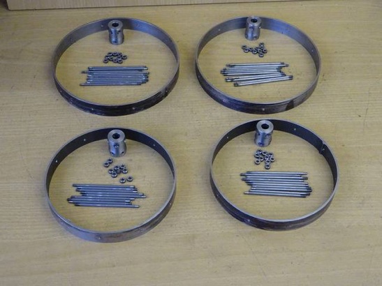
To assemble the wheels each spoke had one of the bosses loosely slipped over it then the threaded end was dipped in JBWeld and screwed right into the hub following which the other end was snapped into the hole in the rim. This got a bit more difficult as more spokes were added. Once all were in, the spokes were unscrewed a couple of turns until the full dia started to touch the rim at which stage the wheel was held in the lathe and the spokes tweaked to get the rim to run true much like you would true a bicycle wheel. Finally the bosses were stuck into the counterbored holes then set aside to dry.
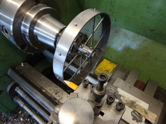
All that remains to do is rivet over the ends of the spokes, tidy up the dried JBWeld into neat fillets and then pop the wheels into the lathe to bore out the hub to finished size which should help get them running totally true.
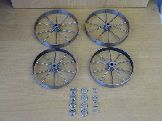
part one here part two part three part four part five part six










Modelengineeringwebsite.com -
the only weekly magazine for model engineers Editor: David Carpenter
