Part 16 by Jason Ballamy
Conclusion - the ‘stone’ base




Part 16 by Jason Ballamy
Conclusion - the ‘stone’ base
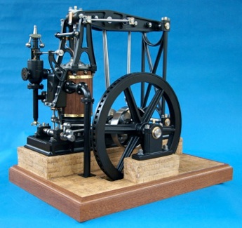
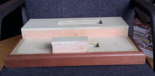
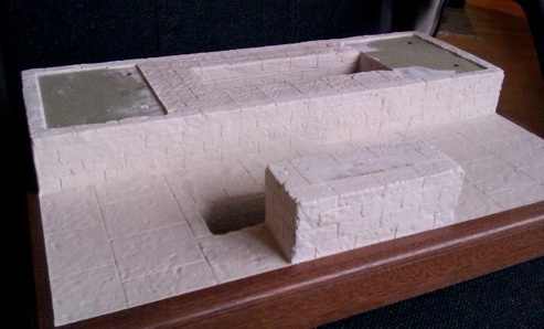
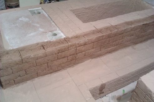
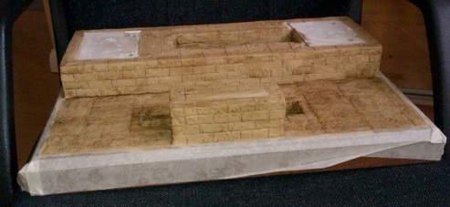
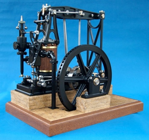
To conclude, I'll detail how I made the base for this engine. A few strips were ripped off an old salvaged mahogany shelf, run through the planer and a simple moulding cut on the spindle moulder but similar could be done with a router. These were then cut with the mitre saw and fixed to the edge of a 12mm MR MDF board. A "box" was made to stand the engine on and a few off cuts glued together to form the plinth for the outboard bearing block. Holes for the flywheel and pump pits were cut and lined with more MDF. Overall size is approx 450mm x 300mm (18"x12").
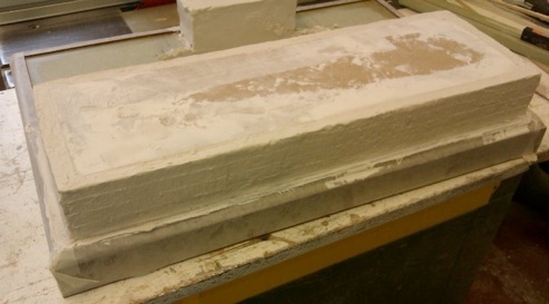
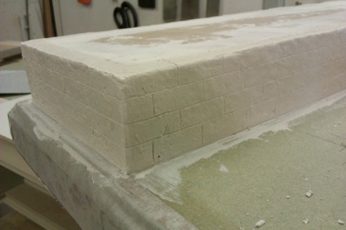
Then the pattern of the joints was scribed into the soft filler with the back of a snap off knife blade. I cut a few scraps of MDF to the stone size and stacked them one on top of the other to scribe each successive course. The verticals were done by eye from a marked out ‘rod’ making sure that the bond carried around the plinth.
MEWS IS SPONSORED BY - BRISTOL EXHIBITION - HARROGATE EXHIBITION - TEE PUBLISHING - MERIDIENNE EXHIBITIONS - LYNX MODELS - CAMDEN MINIATURE STEAM - TRANSWAVE CONVERTERS - MESSE SINSHEIM - CHRONOS - PAULTHECAD.CO.UK - ECCENTRIC ENGINEERING - WARCO -