REEVE’S GRAVITY ESCAPEMENT REGULATOR
Hywel Lambert

REEVE’S GRAVITY ESCAPEMENT REGULATOR
Hywel Lambert


Hywel Lambert showed this clock at a Bristol exhibition. It is a regulator with a gravity fed escapement designed by Claude B Reeve. His design from 1960 was later re-visited by John Wilding.
Describing the clock Claude Reeve noted that a regulator with gravity escapement was seldom seen and that although the Graham dead-beat escapement gives a very good performance, a gravity escapement will do as well and has certain advantages over the dead-beat escapement. He made three clocks with gravity escapement. The first of them had been going more than 20 years and gave the best performance of them all.
“The late Lord Grimthorpe who brought gravity escapement to its present development stated that the wheel train need not be so perfect as that required for a dead-beat escapement. From experience, however, I would say that the wheel train for a gravity escapement clock cannot be too perfect. Imperfections in wheel cutting or wheels out of poise show up when the movement is in action owing to the large angular rotation of the escape wheel at each beat. Such imperfections would be quite undetectable with a dead beat escapement.”
Claude’s guide
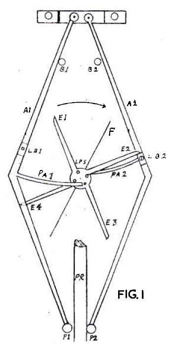
Before describing the construction of the clock a short account of how gravity escapement works may be useful. The escapement as shown in Fig. 1 is invariably positioned at the back of the movement. The teeth of the escape wheel are marked E1, E2. E3 and E4. At the centre of the escape wheel are four pins LPS each of which is in line with the radii of the escape wheel teeth. There are four similar pins on the reverse side of the escape wheel between the radii of the escape wheel teeth but these are not shown in the drawing.
Action of the escapement
As the wheel rotates, these pins raise alternately the two gravity arms which, in falling, rest on the pendulum rod which is thereby given a constant impulse by gravity.
The escapement works as follows. The escape wheel turns. clockwise and a lifting pin on its further side (not shown) lifts or pushes the pallet (P A2) which is in one piece with the gravity arm (A2) outwards to the right.
The effect is to unlock the tooth (E2) of the escape wheel which at once rotates 45 deg. until arrested by the tooth (E4) which locks on the locking block (LB1)
Meanwhile, the impulse pin on gravity arm (A2) is resting against the pendulum rod (PR) impelling the latter to the left. Before the pendulum rod reaches the zero position the gravity arm (A2) is arrested by the banking pin (B2) freeing the pendulum rod of the impulse pin for a short distance. Precisely the same action occurs with the left-hand gravity arm (Al). A fly (F) is fitted to the escape arbor to equalize its motion during rotation. It will be seen how slight is the impulse needed to keep the pendulum vibrating, for the gravity arms hang fairly vertically and are extremely light in weight.
In the clock to be described, the arrangement of the escapement has been modified to bring it to the front of the movement where it can

A general view of the movement as seen from the front is shown in Fig. 2. The back plate of the movement is not shown. Items shown in Fig. 2 include the great wheel (GW), the winding drum (WD) for the weight line, the centre wheel (CW) or minute wheel. the third wheel (TW), the fourth wheel (FW) or seconds hand wheel, and the escape wheel (EW). The three small circles and the large circle in full line drawings are the motion wheels which will be described later. Note that the gravity arms (AI) and (A2) do not extend beyond the pallet arms (PA1) and (PA2).
From a comparison of Fig. 2 with Fig. I, it will be seen that the escape wheel rotates in the reverse direction, due to the escapement being brought to the front. In Fig. 2 the large maintaining ratchet wheel (MW) is superimposed over the great wheel and behind the smaller ratchet wheel attached to the winding drum. Also shown are the maintaining click (MC), and the jockey pulley (JP) which takes the driving line from the drum of the great wheel.
Bridges are attached to the front and back movement plates to carry the pivots for the extended arbors of the gravity arm. The cross in the centre of the front plate carries the extended pivots of the escape wheel and seconds wheel's arbor, and on the front pivot of the latter is fixed the long seconds hand. Near the base of the cross is an end view of a pinion which is attached to the intermediate minute wheel. This wheel revolves on a stud attached to the cross, below the intermediate minute wheel and in mesh with it is a similar minute wheel.
In mesh with it, is a similar minute wheel fitted friction-tight to the extended front pivot of the centre wheel. Above the intermediate minute wheel and also in mesh with it, is a similar minute wheel which carries the minute hand. This wheel rotates on a tube fixed to the cross. Superimposed and revolving on the hub of this minute wheel is the large hour wheel which carries the hour hand. The teeth of this hour wheel mesh with the leaves of the pinion attached to the intermediate wheel, the whole arrangement thus producing a movement with a centre second hand.
Towards the base of the front movement plate is a bridge, which carries the front pivot of the arbor and winding square. To this is attached the reverse winding gear, which meshes with a similar winding wheel attached to the extended front pivot of the arbor of the winding drum. A small steel friction spring (FS) is fitted to the extended pivot of the arbor of the centre wheel to connect the minute wheel previously described.
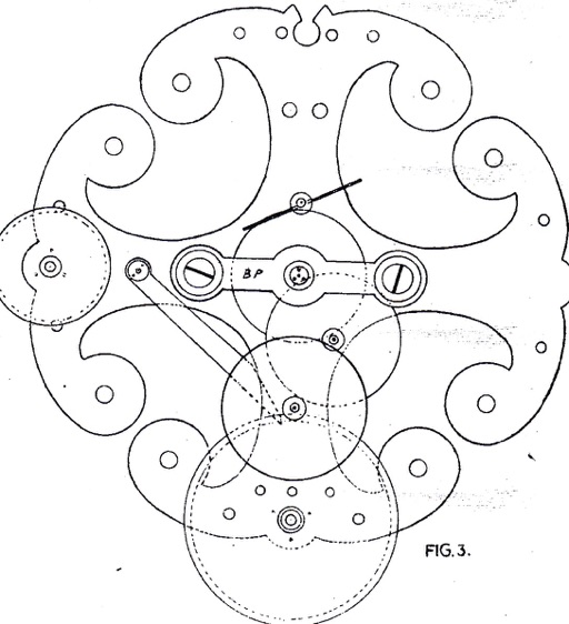
Fig. 3 represents the inside view of the front movement plate with the wheels in position. Note the bridge piece (BP) which carries the pivot hole bush of the pivot of the shortened arbor of the seconds wheel.
John Wilding’s construction book is available here.
