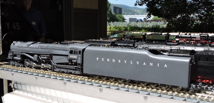
PENNSYLVANIA RAILROAD TURBINE LOCOMOTIVE
Part 1 by Werner Jeggli

PENNSYLVANIA RAILROAD TURBINE LOCOMOTIVE
Part 1 by Werner Jeggli
With my LMS Turbomotive up and running, what next?
Why not retrace history, I thought. The Americans were so impressed by the English engine that they decided to follow this lead - but the engine had to be bigger and better (of course). In 1944 the Pennsylvania railroad took delivery of the locomotive. It made successful runs but operational problems and the twilight of the steam era led to its demise. In 1949 it was withdrawn from service and subsequently scrapped in 1952.
This is a rather sad story. The challenge of modelling this engine successfully as a turbine driven gauge 1 model was therefore all the greater! Nevertheless, I decided to have a go at it. Simon Duhamel in France pointed me to The Keystone, Volume 45, No.3, a publication of the Pennsylvania Railroad Technical & Historical Society, which provided me with the necessary technical information, including detailed outline drawings.
Based on the experience gained with my three previously scratch built turbine locomotives, taking into account the expected power requirements of the much larger American engine and using the results of my turbine wheel investigation I established the following design criteria:
1. Boiler capable of vaporizing at least 1.7 l/hr water at 3.5 bar.
2. Turbine shaft power output at 35,000 rpm forward at least 8 Watt.
3. Driver unit pull-up torque forward 1.5 times the max. speed torque (power required for train acceleration).
4. Locomotive internal friction losses at design speed (without tender) max. 4 Watt.
These criteria serve also as milestones. This means that design and construction of the engine will not proceed as long as the milestones are not reached in the above order.
Turbine shaft power output will be electrically measured on a test rig. The locomotive itself will have a purely mechanical drive; design speed and gear ratio is to be determined based on the actually produced turbine power output.
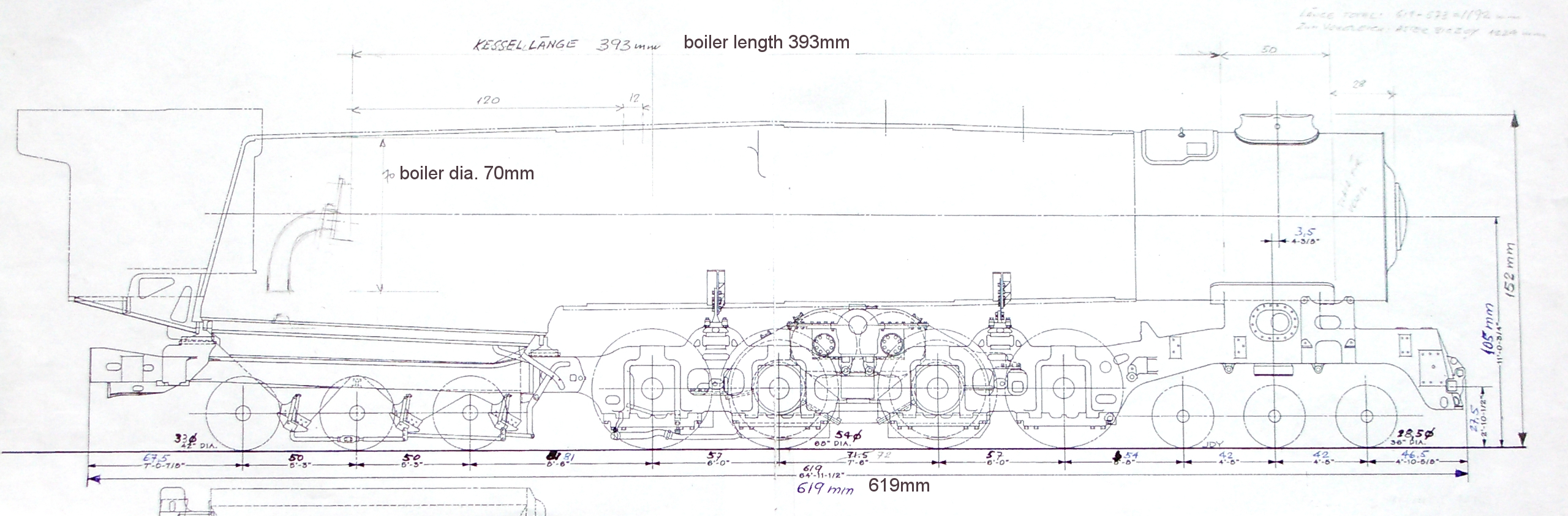
Boiler
First the boiler has to be built. Its maximum dimensions can be taken from the relevant drawing (above). Steam demand for such a large locomotive is high, and an easily controllable heat input is of advantage, hence gas firing is the choice. To save on weight (mass, which has to be accelerated and braked) and to reduce thermal losses the outer shell of the boiler was to be of 0.5mm stainless steel. Inside however, copper would be advisable for heat conductivity reasons. Welding or brazing of the two different materials is a no-go. Flanges must be provided to bolt and seal the two sections. To reach the specified steaming rate, two Bunsen burners would be used. The large American railway profile luckily allows for two gas fired combustion chambers side by side.
The boiler was then built and pressure tested to 10 bar. A prototypical turbine/generator unit with two 0.8mm dia. steam nozzles and the lost wax bronze cast wheel was assembled. Tests to verify milestone 1 were conducted February 2016. The test arrangement and components are shown in photos 1 - 5. Result: Steam generation is 145g x 12 = 1740 g/h. Milestone 1 therefore was met.


3. Boiler hot, liquid gas feeding mode, gas pressure is maintained.


Taking generator/rectifier efficiency into account, the turbine shaft output of the experimental turbine is close to 10 Watt. Milestone 2 also OK!
Engineering could now proceed. At a turbine speed of 35,000 rpm I expected to have at least 4 Watt available at the locomotive hook. Maximum scale design speed is 130 km/h (my decision!) which works out to 1.12 m/s on our track. The PRR S2 driver diameter is 0.054 m. To reach this speed, the drivers have to rotate at 6.6 rps (396 rpm). This then requires an overall gear ratio of 35,000/396 rpm = 88.4:1. The closest ratio I could implement was 84:1. So, I left it at that.
Expected maximum hook force at that speed should then be 4W divided by 1.12m/s = 3.6 N (≈ 360 g), absolutely sufficient to pull most that I would use.
Next, gear drive and loco frame had to be completed to prove milestone No.3. A wooden driver of correct diameter was installed (photo 6). Target pull was 1.5 x 3.6N = 5.4N (approx. 540g). At 4 Bar, 850g (8.5N) was measured (July 2016). OK!
Construction could continue.

The skeletons of locomotive and tender were built and successfully demonstrated at the Eisenbahn Witterswil (EiWi) Bahndammfest, July 2017, in Switzerland.
To the delight of the many fellow steamers and spectators they pulled a rake of four heavy J&M Pullman coaches for three quarters of an hour around the track, at low and high speeds - perfectly remote controlled by a Peter Spoerer TX 2.0 system.
The result could be summarized as follows:
1. The locomotive’s boiler and turbine drive is up to the task.
2. Automatic burner rate reduction on reaching maximum operating steam pressure and bimetallic dry run protection are operational but need tuning and operating experience.
3.The stainless steel gas tank in the tender is big enough to supply gas for an hour’s run. Its 3-way gas/liquid take off valve is essential for prolonged operation.

The tender also houses an electric motor driven boiler feed pump of my own make, controlled by a level sensing system. Interest of the live steamer fraternity is focused (understandably) on the turbine drive unit. However, it is perceived as a complicated, difficult piece of equipment to produce. In my opinion, a piston drive is much more demanding. A turbine rotor can be machined on a small mill or can be lost wax cast (as in the present case) provided you are in a position to generate the required file for the wax 3D print. For steam nozzles, portion of a doctor’s injection needle can be used (1.2mm od. / 0.8mm id.) and for the turbine bearings, hybrid ones with ceramic balls and steel casings will do. A squirt of WD 40 prior to each run has proven to be adequate. And remember: no steam oil required!


and one reverse 0.8mm diameter nozzle openings
visible.


admission valve added.

added.

At this stage it seemed that just cosmetics would see the project complete!


