LOW COST DISC BRAKING FOR MINIATURE RAILWAYS
By Bert Roberts


LOW COST DISC BRAKING FOR MINIATURE RAILWAYS
By Bert Roberts

Over the years, caliper disc brakes have become the norm across many braking applications. However, the size and cost of the calipers has made them difficult to incorporate into the braking systems of carriages and driving trucks for miniature railways, especially 5” gauge.
Around 12 years ago, at Ashton Court Railway, Bristol, Ron James and Phil Bridgeway came up with a very successful design for using brake disc calipers on the 7.25” carriages, using a vacuum for operating the brakes. This design was based upon ‘Hayes’ calipers that cost around £80 each.
Some years ago, with the help of Ron James and Andy Harding, I came up with a design for having two calipers per bogie on my 6ft carriage that has been used for public running over the last 3 years. This design uses ‘mini-moto’ calipers costing around £12 each.
Since then, I have refined the design and have recently built a small fleet of caliper braked, 5” bogies that come in at around £260 a pair which excludes a few home-made components. One of the benefits to using disc brakes is that efficient braking is achieved using lower actuator forces than with other means of braking resulting in lower wear rates of the braking components making them virtually maintenance free.
Small disc brake units, as fitted to go karts and Mini-Moto bikes, are now affordable and whilst the high-end units for go karts cost around £100 each the ones intended for Mini-Moto bikes start at around £12 each and are perfectly adequate for our needs. Space is obviously a consideration, but these units are effective even if the operating arm needs to be shortened a little.
A single caliper on each bogie of a 6ft carriage will provide adequate braking when fully loaded with operation via a Bowden cable for driving carriages. A motorcycle sized cable would be preferable to a cycle cable though.
The calipers are readily available from eBay or on the internet, two companies that sell them are Pitspares and Petrolscooter.
There are several variations to the overall construction and appearance of these units including the orientation of actuating arm. It is possible to make some adjustments to improve the installation in the carriages as indicated in the basic diagram.
Mini-Moto caliper basics.
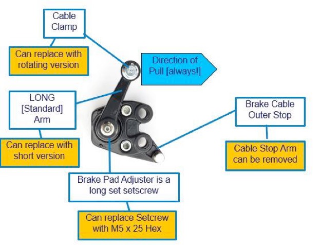
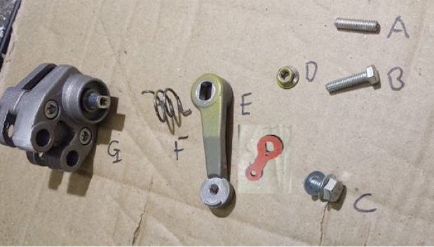
Main components and options
A & B: Brake pad Adjusters:
This adjusts the gap between disk pad and brake disc.
Replace standard adjuster [A] with [B] as this is easier to adjust once caliper is installed.
[B] is an A2, stainless, M5 x 25 hex bolt.
C: Cable Clamp [as supplied]: This may be unsuitable as it locks the cable to the arm and stresses the cable when brakes are applied. Consider a “rotatable” clamp.
D: Actuating Arm Locking Nut: Clamps arm [E] to the actuating mechanism.
E: Actuating Arms: The longer one (yellow end) is the standard. However, the braking system performs well with a shorter one [red].
F: Actuating Arm Return Spring: This returns the Arm to the at-rest position. As “standard” this will only suit ONE orientation that is determined by pre-drilled holes.
G: The Brake Caliper itself
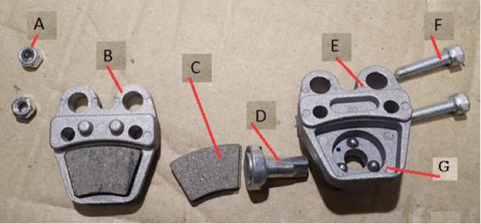
Brake caliper basics – internals
Ref photo on next page.
A: Clamp Nuts [Nyloks] – sit within rear of item B
B: Caliper Body LHS - contains a fixed brake pad
C: Moving Brake Pad – that sits within E and moves up against the Brake Disc
D: The WORKING BIT!! – this is rotated by the Actuating arm that is bolted to one end. At the other end it contains a circular ramp that moves over the ball bearings [in item E] causing the brake pad to move towards the brake disc [not
shown]
E: Caliper Body RHS – This contains and constrains the major components that move the brake pad up against the brake disc [not shown]
F: Caliper Clamping Bolts – these hold Parts B and E firmly together when tightened up against Items A
G: Ball Bearings that facilitate rotation of Item D up to its stops
The arrangement of the three ball bearings means that the actuating arm can be set in any one of three orientations [at 60 degrees] BUT the Arm Return Spring [and thus the arm] will [as standard] only fit in ONE place as only one set of drilled holes are provided.
Assembling the units to the required orientation is fiddly and the ball bearings are prone to moving out of their recesses.
Installation
The calipers are mounted in such a way that they self-centre in an identical manner to caliper/disc braking systems of cars, so this is NOT an issue where the caliper can move laterally with the disc.
A caliper has an internal return spring. However, it may be necessary to have an extra compression spring in the line due to resistance in the lengths of brake cables required. The cable would usually be operated by a hand lever or a conventional cycle brake lever.
When the caliper is in-situ, the Brake Pad Adjuster is used to adjust the pads up to the brake disc, ensuring that there is clearance for the caliper and disc to move relative to each other without binding.
If more than one caliper is fitted then a brake compensating device will be required. This is a simple device that shares the brake pull between all the calipers as necessary.
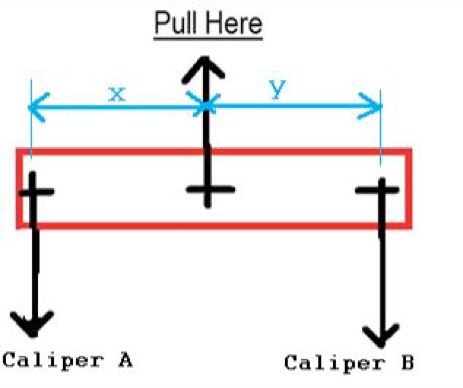
A Compensator can be simply a floating bar where ‘Pull’ is connected to the brake actuator.
The Pull is shared between two other points at distance “x” and “y” which are determined to bias the brake effort to suit the application.
Caliper A and B are where the Single Pull is distributed to calipers [or can be to bogies]
Typical installations
The illustration below is an example of a single caliper fitted to a 5” bogie. The return spring on the cable is an added extra which is determined by experimentation.

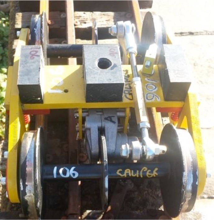
Twin caliper installation.




Modelengineeringwebsite.com
the only free and the only weekly magazine for model engineers.
Editor: David Carpenter