REINVENTING THE REAL
Part two by Jason Ballamy

REINVENTING THE REAL
Part two by Jason Ballamy

As I had cut off a bit of 12mm PGMS to use as a plug gauge for the flywheel hole, I thought I may as well work on the crankshaft next.
Starting with a piece of the 20mm square bar I had bought for the column bases it was machined down to an oversize rectangular section and then thinned further at the pin end followed by reaming the holes for the shaft and pin.


While I had a bit of time to spare a small part was ticked off the list in the form of the valve rod clevis. I often mill mine on small square, hex and rectangular components from round stock as it's often not worth buying a 300mm length of a size you won't use much plus some small square stock is not that crisp and often comes with rounded corners. After milling the slot was formed with a 1.5mm slitting saw then the part was cut off the parent bar. I used a square collet but the 4-jaw will do to hold while the end was turned, drilled and tapped, I'm using a 2mm radius tool which like the milling cutter mentioned above leaves a pleasing small internal fillet.


As I said in the introduction the one supplied by Stuarts is little more than a rectangle with rounded corners and a bit of draft angle which only needs flattening on the bottom, skim cut off the top and a few holes added which does not give you much workshop time for your money as it should not take more than an hour to do.
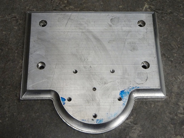
I opted for aluminium as it's easy to cut and no more expensive than bright steel flat. I've not noticed any problems with my other models that use aluminium right from the early ones I made 30+ years ago like the Minnie which has several aluminium castings through to others with aluminium castings and the ones I have fabricated using the material. Even Stuarts have used it to cast the fluted column of the Williamson.
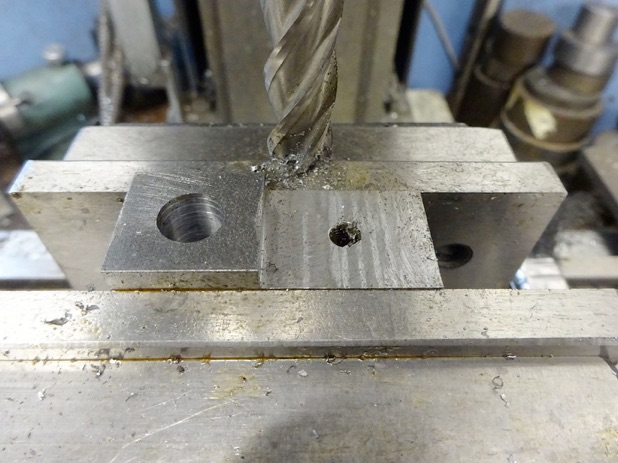
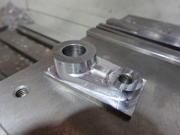
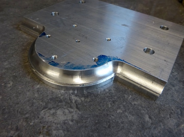
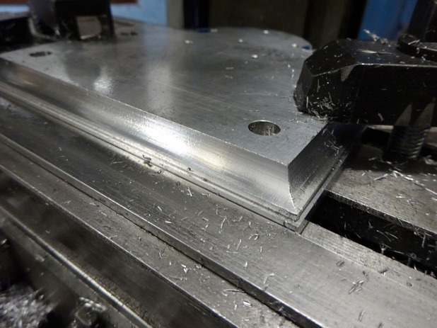
So starting with a piece of 12mm material it was sawn slightly oversize and clamped to the mill table on some packing so that three sides could be milled square to each other. I then drilled four hole 5mm which were later countersunk on the underside for M5 CSK socket screws. These holes were also counterbored from above by plunging with an 8mm 3-flute cutter to form sockets that spigots on the column bases will fit tightly into so they locate accurately. I also drilled and tapped M4 for the studs that will hold the cylinder cover in place and at the same time added a small hole to use as a datum at the centre of the cylinder position that could be used to locate the base on the rotary table if using that to mill the half round.


Modelengineeringwebsite.com
the only free and the only weekly magazine for model engineers.
Editor: David Carpenter