The Simpson and Shipton engine has been the subject of designs by Anthony Mount which was described in the 1990s, another by by Julius de Waal. Drawings for Anthony’s model are available in Volume 2 of his book Historic Engines Worth Modelling, available from TEE Publishing. Julius’ drawings are available here.
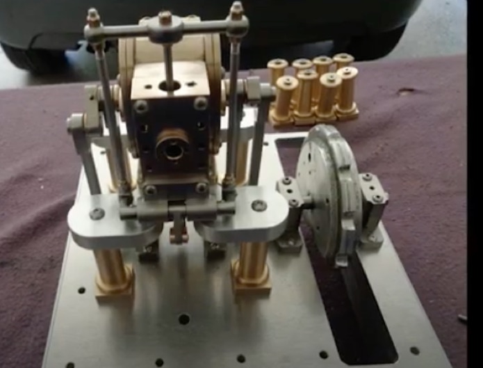
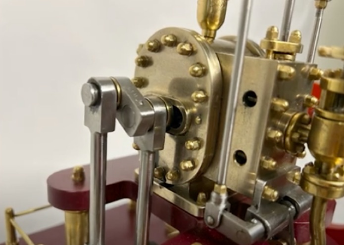
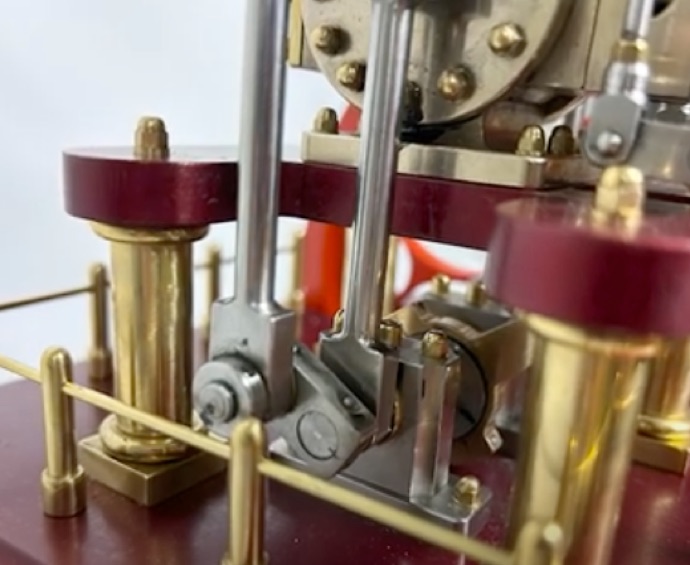
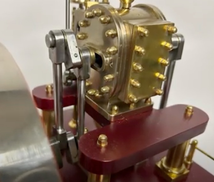
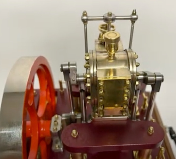
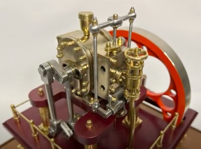
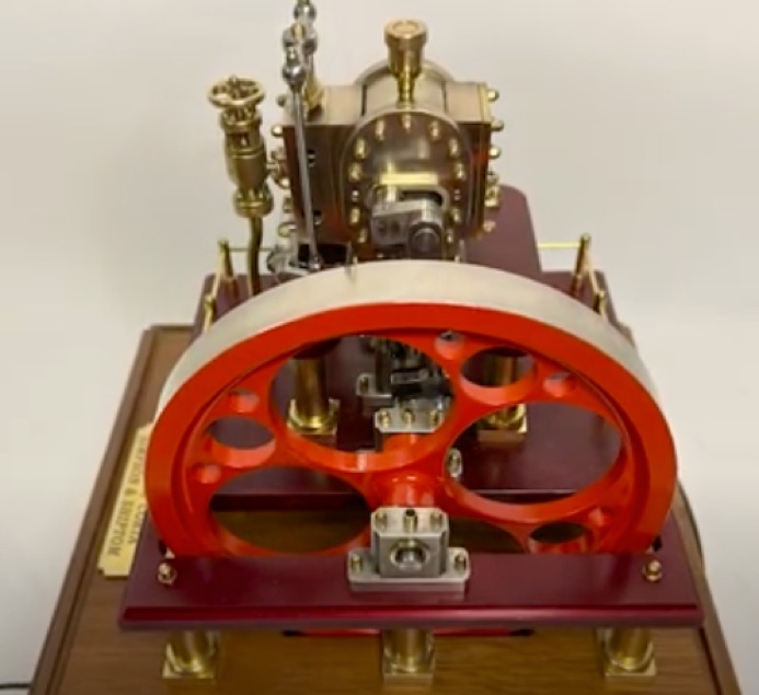
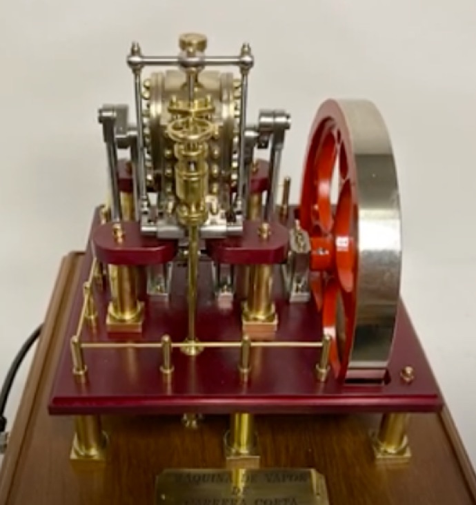
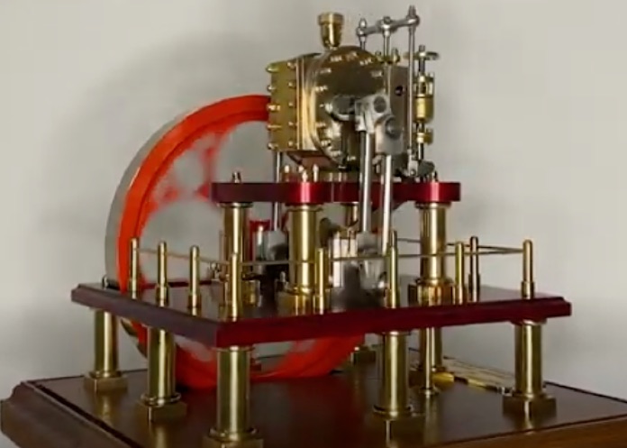
The engine is described by Anthony as a rotary steam engine, but it still uses connecting rods to drive the crankshaft. The ‘cylinder’ or perhaps better described as a chamber, sits on a table carried on four short columns. Inside the chamber is a ‘piston’ lying on its side. Passing through the piston is an eccentric shaft, connected to the outer ends of the shaft are cranks. Connecting rods drop from these cranks to the crankshaft carried on bearings fixed to the base. Steam enters the chamber through a balanced slide valve and impinges on the side of the piston rolling it around inside the chamber.
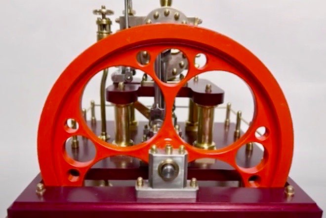
Anthony explains that “The engine does look very interesting when in motion, there are levers gyrating all over the place. It is also very free running and only requires a wisp of air to get it running. How many of these engines were built full size is unknown, but an engine was exhibited at the great exhibition in 1851 where it drove textile machinery. There is also a reference to the engine in The Engineer in 1862. Still with the same cylinder arrangement, but with a different drive mechanism.”
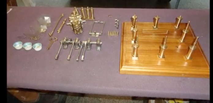
He adds: “Construction of the model is quite conventional without any odd machining practices. It can be machined on a 3 1/2” lathe, the flywheel being 9” (225mm) diameter. There is quite a lot of milling involved, and while this could be done using a vertical slide. A vertical milling machine does make things a lot easier.”