
MENTION Stuart Turner steam engines to most model engineers, and they will probably recall the iconic No1 from the 1890s or the more prolific No 10V or S50 engines. This article covers the evolution of the enclosed model marine engines from the early 1900s to the Sirius which remained available from Stuart Models up to 2007/8.
Unlike most contemporaries of the time, these Stuart Turner engines were made to do meaningful work and were based on sound engineering practice. They used the highest quality of ‘correct’ materials and offered a long and trouble free working life.
At the time, a number of full-size engines were available. These include, Wilans, Westinghouse and Peache. There can be little doubt that these Stuart Turner engines owe their functional looks and some design features to this full-size practice.
The engines in this range are all twin cylinder single acting and were designed specifically for fast power boats or the Model Torpedo Boat Destroyers (MTBs) which were in vogue at the time of the initial production. The reasoning, by Stuart Turner, was the engine should be of minimal weight compared to the power produced, have a minimum of working parts and take up very little room within the boat, particularly headroom, which may have been very limited due to the lines of the boat.
This view is echoed by Edgar T Westbury in 1955 who added: “Single-acting engines can be made with much lighter reciprocating parts than double-acting engines, because the piston needs neither a piston rod nor crosshead and can be of very light section. The applied pressure is transmitted by a connecting rod to the crank in the most direct manner possible. This favours high mechanical efficiency, which is further promoted by the elimination of piston rod packing glands, which are often a source of considerable friction” and “The height of the engine is greatly reduced by elimination of the crosshead and piston rod and this not only makes it more compact, especially in the dimension usually most important, but also cuts out a good deal of the structural weight”.
He goes on to say, the later engines in this range, the Star, Sun and Sirius are all capable of high power output for their working speeds up to 4000 rpm or above. He recommended that for speeds up to 1000 rpm, orthodox or double acting engines provide excellent results but for higher speeds single acting engines with light pistons and simple valve gear are most suitable.
Reading Westbury’s The History of Model Power Boats the majority of engines shown are of the enclosed type, ranging from single to triple cylinders and from what can be seen, they appear to be single acting. A number of points are, perhaps, obvious. The modellers/competitors were more interested in the authenticity of looks or design of their boats and performance. The engine/boiler combination, and later radio control systems, appears to be secondary considerations. Given a well designed, compact and powerful engine with an efficient boiler – they appeared to be happy. Stuart Turner had made his products appropriate for the market!
The range was launched prior to 1909; they are not included in the 1904 or 1906 (reprint) catalogues. Complete catalogues before 1909 are now very rare. Strangely, there is only one review of these engines - the Sirius - in Model Engineer magazine which traditionally reviewed or commented on any product or activity by Stuart Turner Ltd.
The range started with three engines, No 1 MTB, No 1a MTB, The Featherweight, and No 2 MTB. Each engine was quite different. Nobody could accuse Stuart Turner of being fanciful in naming his engines!
No 1 MTB

This engine has two longitudinal (in-line) cylinders each of 0.75” bore and 0.75” stroke with slide valve gear. This was claimed to provide a perfectly balanced engine.
It is constructed from traditional materials, four cast iron castings (cylinder block, crankcase, cylinder head/steam chest and steam chest cover), steel crankshaft and valve gear. A 1.50” diameter 0.625” thick steel disc wheel was provided. An exposed cam driven valve gear was used (this is not an ordinary eccentric) where friction was reduced by an innovative arrangement of a steel ball held up to the cam lever by a spring.
The engine was designed for use as a single engine in a boat up to 4’ 6” in length or the use of two engines for twin screw boats up to 5’ 6” long (Class A). The design is compact being 4.50” long, 2.50” wide, 3.75” tall with a weight of 2 lbs.
It was available as a finished, complete, ready to run engine or as a set of castings and materials.
No 1a MTB (The Featherweight)
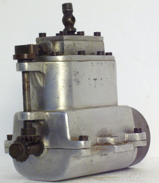
Launched in 1909, this engine is of the same design as the No 1 MTB with cylinders each of 0.6875” bore and 0.6250” stroke with slide valve gear. It is constructed of two aluminium castings for the cylinders and crankcase, with pressed in cylinder liners of hard triple drawn brass, and hard aluminium alloy castings used for the steam chest and cover. A 1.50” diameter 0.625” thick steel disc wheel was provided. The valve gear is driven by two exposed bevel gears which created a precedence for this type of engine.
The engine was specifically designed for light displacement, typically thin metal, boats. It was claimed to be suitable as a single engine in 1 Metre (Class C) boats or as two engines, twin screw, boats up to 4’ 6” long. The design is very compact being 4” long, 2.75” wide, 3” tall with a weight of 14.5 ozs.
With 30 lbs of steam, it was noted this engine ran at 2500 rpm light and 1500 rpm under load. It ran equally well without a disc wheel – which was a tribute to its balance.
It was available as a finished, complete, ready to run engine or as a set of castings and materials.
The No 1a The Featherweight remained available up to the late 1920s, it does not appear in the 1930 catalogue.
No 2 MTB

Unique in the entire Stuart Turner range, this engine has two transverse cylinders each of 0.75” bore and 0.75” stroke with slide valve gear, driving two contra-rotating geared drives with integral disc wheels.
It is constructed from traditional materials, three cast iron castings (crankcase/cylinder block, cylinder head/steam chest and steam chest cover) , steel crankshaft and valve gear using an exposed steel lever driven valve gear.
The engine was designed for use as a single engine in a boat up to 4’ 6”. The design is compact being 2.50” long, 3.75” wide, 4” tall with a weight of 1 lb 14 ozs.
It was available as a finished, complete, ready to run engine or as a set of castings and materials.
By 1924, this engine had been dropped from the catalogue.
No 180

Between 1910 and 1924 the No 1 MTB was redesigned and renamed as the No 1b MTB. Most probably, this engine was introduced between 1910 to 1914 or 1921 to 1923 as Stuarts were engaged in war work between 1914 and 1918 and had considerable commercial difficulties between 1919 and 1921.
A number of engines exist with 180 cast on one side of the cylinder block casting and STUART on the other side.
Comparing the 180 and No 1b MTB side by side, the key dimensions of bore, stroke, length, width, height and weight, the engines are identical. Having measured various other dimensions, crankcase, cylinder head etc I can confirm the castings are identical with the exception of 180 being cast into one side.
I have concluded that 180 is a casting identification number. It is rare for these numbers to be visible but the No 3 MTB Stationary has 255 on the cylinder block casting. Typically these numbers are on the under surface of the castings eg early S50 Mill Engine (330), early No 10H (STUART 218) and Progress Horizontal Oscillator (STP1).
I further conclude, that the 180 is an earlier production version of the No 1b MTB. Basically, remove the “180” by filing or machining and you are left with an identical engine to the No 1b MTB.
The key difference between the 180 or No 1b MTB engines and the original No 1 MTB is the valve gear drive has been replaced with a pair of bevel gears similar to those fitted to the No 1a MTB. It can only be assumed that this change was introduced because the original cam driven lever system proved too complex and, possibly, unreliable for prolonged use.
No 1b MTB (and 180)

This engine has two in-line cylinders each of 0.75” bore and 0.75” stroke with slide valve gear. It is constructed from traditional materials, cast iron castings, steel crankshaft and valve gear. A 1.50” diameter 0.625” thick steel disc wheel was provided.
It was stated this engine was suitable for ordinary and flash steam making it suitable for ordinary cruising or racing. Internal lubrication is “by splash” and a Stuart Displacement Lubricator was recommended for lubrication of the valve gear and cylinders. The engine was designed for use at very high temperatures and pressures.
The exposed cam driven valve gear has now been replaced with exposed bevel gears, similar to the No 1a MTB.
As with the original No 1 MTB, the engine was designed for the same size of boats and had the same dimensions.
It was available as a finished, complete, ready to run engine or as a set of machined and finished parts and materials or as a set of castings and materials.
A number of versions of this engine exist. The main differences being the length of the support brackets for the valve gear driveshaft (earlier versions, 1” long, later versions reduced to 0.625”) and the gland on the valve gear. Early versions had a brass hexagonal threaded gland and later versions with a brass oval section gland fixed by two studs. Clearly, a revised valve chest casting was required.
The No 1b MTB was replaced by the Sun engine in 1927.
Figures 6 to 9 show the variations of valve gear drives. My experience of the valve gear on the No 1 MTB shows it to be unreliable. The steel ball has a tendency to fly off the cam, and across the workshop, leading to the obvious timing problems. Perhaps, not the ideal situation when your boat is going flat out!
The problem being, there is a small indent at the end of the lever which holds the ball in place while being forced against the cam by the compression spring at the top end, as the ball transits the low and high faces of the cam (minimum and maximum travel of the slide valve) it tends to loosen and fly out.
I have seen a few of these rare engines and this appears to be the most common method of retaining the ball. I have seen one variant where the ball has been replaced with a horizontal “doughnut shaped” steel bearing held in a fork at the end of the lever. Whether this was a modification by Stuarts or an ingenious model engineer to overcome the problem will, probably, never be known.

The end of World War 1 saw the model boat community moving away from traditional steam engines for competition purposes toward petrol engines, of which Stuarts made a range, and flash steam with the preference for Single Acting Piston Valve engines.
To combat a, probable, decline in sales of the No 1b MTB Stuarts focussed on another market. From around 1924, they introduced a number of cast bedplates to enable this engine, and others, to be directly connected to dynamos and centrifugal pumps (see Figure 10).
No 3 MTB and No 3 MTB Stationary

Figure 11: No 3 MTB, from the original catalogue illustration.
Compared with engines ‘in the metal’ this illustration and the one for the stationary version appear highly stylized particularly around the steam chest, valve gear drive housing and the disc wheel.
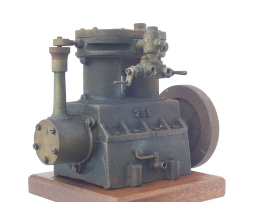
Figure 12: No 3 MTB Stationary
These engines were probably designed between 1910 to 1914 or 1921 to 1923. They appear in the 1924 catalogue almost as an afterthought, the catalogue description being sparse by Stuart’s usual standards. In the actual engines the cast iron castings are not of the usual Stuart crisp and clean quality.
Both engines are essentially the same, the exception being the lower cylinder crankcase casting. On the No 3 MTB, this casting appears to be very slightly lower and convex in lateral section with a mounting lug at each corner to enable easier fitting into a boat keel (see Figure 11). The Stationary version has a deeper, rectangular shaped, casting with two mounting lugs on each side (see Figure 12).
These engines have two in-line cylinders each of 1.25” bore and 1” stroke with slide valve gear. They are constructed from traditional materials, three cast iron castings (combined cylinder block/steam chest, crankcase and valve gear/steam chest cover), steel crankshaft and valve gear. The valve gear is driven by two bevel gears which are of a larger diameter than the other engines. The valve gear drive mechanism, including the two bevel gears, is enclosed in a well designed and cast brass housing with cover. A 3.625” diameter 0.50” thick steel disc wheel was provided as standard.
They are considerably bigger than the previous engines being 8.25” long, 4.0” wide, 5.75” tall with a weight of 5.75 lbs.
Both engines have a very unusual feature. These are the only engines I have come across when the cylinder bores are not bored through the casting – they are blind bores. The entire cylinder block and steam chest is a single casting. This must have made machining and lapping the cylinders very difficult, not to mention machining the steam chest and the steam and exhaust ports. This must have made these engines quite unpopular with model engineers of the time considering their limited resources.
The No 3 MTB was designed for marine use, although no boat specifications are provided they must have been very substantial given the dimensions of the engine – not to mention an appropriate boiler.
The Stationary version was suitable for being directly coupled to a dynamo, typically of 120 to 150 watts output. Stuart’s had been providing suitable dynamos from 1906 or earlier.
They were available as a finished, complete, ready to run engines or as sets of castings and materials.
Both these engines were withdrawn from the Stuart range in 1934/35.


