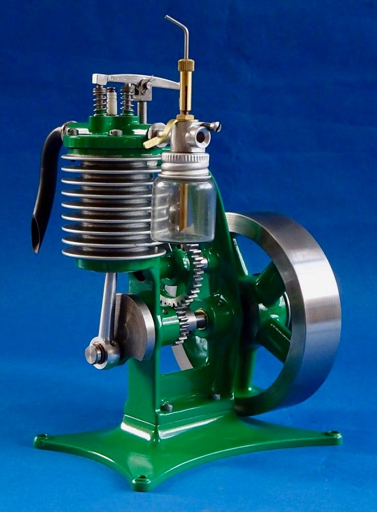
I decided to go for a more shapely base than the original as it gave me an excuse to try a few more things out on the CNC. A piece of 16mm 6082 was rough cut to size on the vertical bandsaw and screwed to a block which in turn could be held in the vice. I tried out a 25mm dia 2-flute indexable cutter for the roughing pass which meant a lot less passes around the work due to being able to use a wide 20mm step over. It worked quite well just getting a bit noisy as I got towards the bottom due to the unsupported edges giving a bit of chatter.
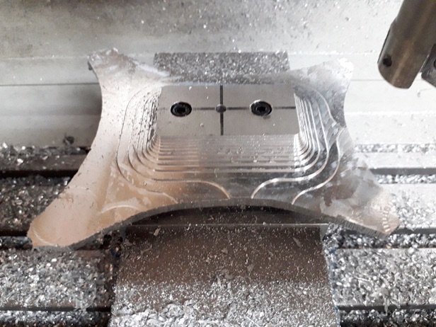
The finishing was done with a 6mm 4-flute ball ended cutter using Fusion 360's Steep & Shallow 3D finishing, it did leave a couple of ridges where direction changed due to what I have now found was a slightly too tight Z-axis. You may also be able to spot that I was short of material on a couple of corners, this was due to positioning the work based on the centre of the top face where the engine fixes but doing the CAM based on the centre of the stock which was about 2mm different.
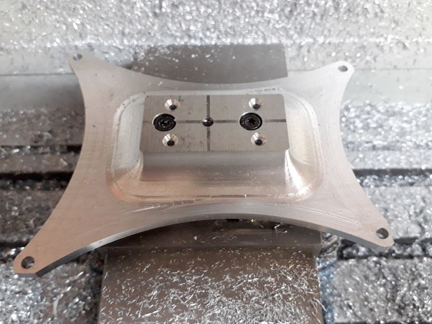
But with a bit of JBWeld to build up the corners and some work with Emery cloth on the ridges it did not come out too bad once a coat of etch primer had been blown on, I've since rounded over the edges a bit more as they look too crisp in this photo.
The cylinder head started as a lump of cast iron bar in the lathe where a 1mm spigot was turned to locate in the cylinder liner before being transferred to the mill where I drilled and tapped what will become the clearance holes for the head screws and also just spotted the position of the two valve pockets.
I was then able to mount the head onto a block of aluminium by screwing up from below which made it easy to hold for shaping the top and edge which was done on the CNC. Still a few ridges left where the mill's head is sticking slightly.
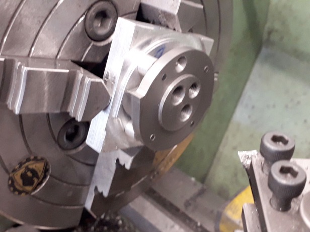
Four spacers were turned up so that the head could be held the opposite way round in the 4-jaw and the valve holes drilled, reamed, counterbored and the seats taper turned all in one setting. Then finally back to the lathe to add inlet and exhaust passages which were tapped M6x1 and M8 x 1 respectively.
Part two here. Part four here.