MY CORLISS
ENGINE BUILD
Part 16 by Vince Cutajar

MY CORLISS
ENGINE BUILD
Part 16 by Vince Cutajar
To finish the connecting rod I calculated the angle of the slanting top and bottom of the fork and marked them.


Initially, I had only marked one side but then I realized that it would be better to mark both sides. Put it in the vice using a mark one eyeball method to line it up with the top of the jaws and proceeded to mill them off.

After some clean up this is how the fork end looked.

Next, the crosshead pin. For this I used a piece of 0.375" stainless. I did the screw first (sorry but no photos) and then the other side. Drilled a 3.3mm hole and counterbored it 4.5mm and then tapped 4mm.

Then the size of the shaft was reduced so that it will pass through the fork. I used the fork as a gauge.
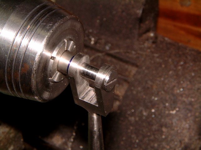
Flipped it around and faced it off and, using a pointed tool, I marked the centre of the face.

I did this so that when I put it in the milling vice it would be easier to locate the centre. Used a 1mm end mill to cut the slot, but managed to break it. So instead I used a 1mm slitting saw to cut the slot.

And this is how it looks with the crosshead installed in the fork.


Modelengineeringwebsite.com
the only free and the only weekly magazine for model engineers.
Editor: David Carpenter

