MY CORLISS
ENGINE BUILD
Part 17 by Vince Cutajar

MY CORLISS
ENGINE BUILD
Part 17 by Vince Cutajar
More work on the guide and bearing support. Started with the guide support and brought it down to size and proper thickness. Next was the bearing support which was also machined to size. Following are some photos of work on the bearing support.


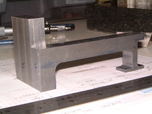
Next thing I did was to reduce the thickness of the bearing support (side frame) from 15mm to 12.7mm.

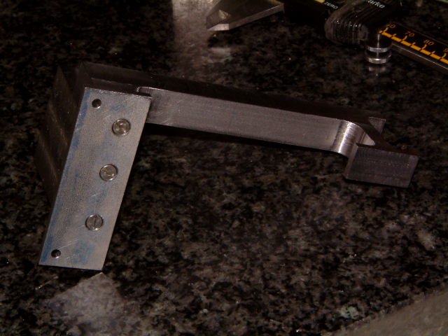
I started work on the front mounting plate. The initial plan was to silver solder all parts together so I managed to find a piece of 2.8mm thick mild steel and made it from that. Problem is it was a bit rusted but that's all I could find.
Well the plans changed and it was decided to screw all the bits together instead of silver soldering. The more I looked at it the more I hated it. So half way through the session I started remaking the plate from stainless. And below the top one is the mild steel plate and the bottom one is the new stainless one.

I did some more work on the assembly, basically screwing it all together.
First job was to mill off about 3mm from the bottom of the front part of the side frame so that the side frame sits level on the foot plate.
Some countersunk holes later and both the front and the side frame are screwed to the foot plate.

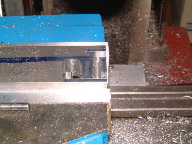
To make the whole assembly more solid, it was decided to add another two screws from the side. The whole assembly was locked in the vice and two 2.5mm holes were drilled. When drilling the second hole, a 2.5mm drill was inserted in the first hole just to make sure that nothing moved.
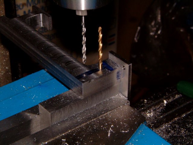
Unfortunately, I could not go the full depth with the second hole due to the other drill sticking out of the first hole. So, the side frame was unscrewed and was able to continue drill the second hole. At the same setting it was tapped 3mm.
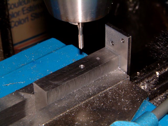
The X-axis was moved to the first hole and was tapped also 3mm. Good thing I remembered the location on the DRO of the first hole!
And here it is all solidly bolted up together.

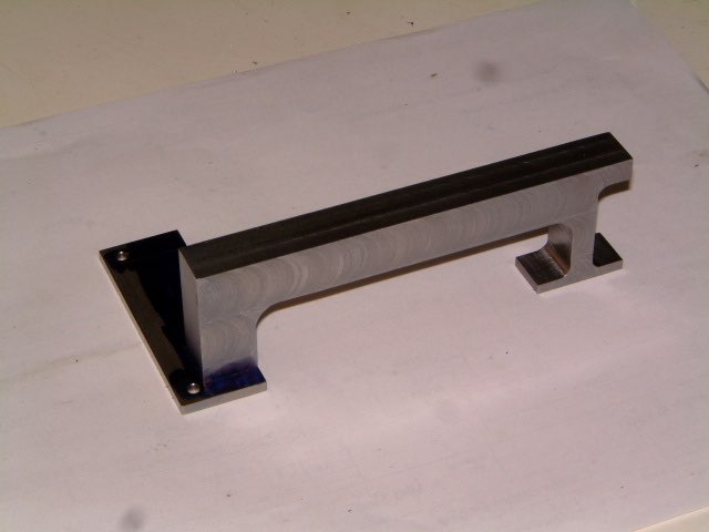
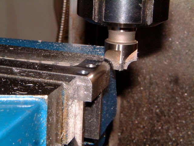
I did the radius cut which is shown on the plans. Actually the plans call for a 0.125" radius but I only have a 5mm radius cutter. So I used that.
The 29mm hole for the crosshead guide was done in the 4-jaw chuck - first step drilled to 25mm.
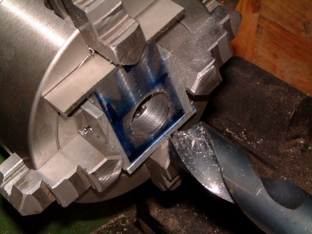
Then using a 12mm boring bar I opened the hole up to 29mm.
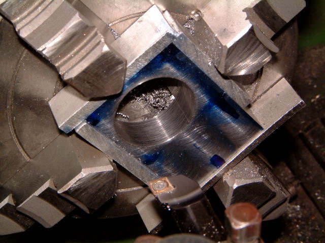
I made the hole a loose fit as I was worried that it might not line up properly with the crosshead guide.
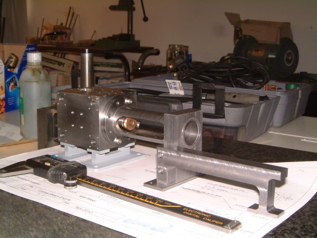
Now for the moment of truth. Assembled everything and wonder of wonders the crosshead guide slipped nicely into the hole. Phew!


Modelengineeringwebsite.com
the only free and the only weekly magazine for model engineers.
Editor: David Carpenter