MY CORLISS
ENGINE BUILD
Part 19 by Vince Cutajar

MY CORLISS
ENGINE BUILD
Part 19 by Vince Cutajar
To fit the valve lever pivot I drilled a 5.5mm hole in the assembly and then opened it up to 6mm with a slot drill to give me a flat bottomed hole. I then chose a piece of 6mm mild steel which would be a press fit in the hole. Faced it to length and then drilled and tapped 2mm.
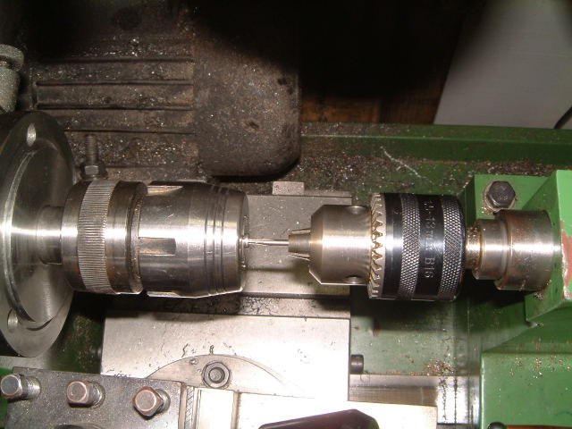
To tap the 2mm hole, I fixed the tap in the tailstock chuck but left the taper loose in the tailstock and turned the chuck by hand. Worked a charm.
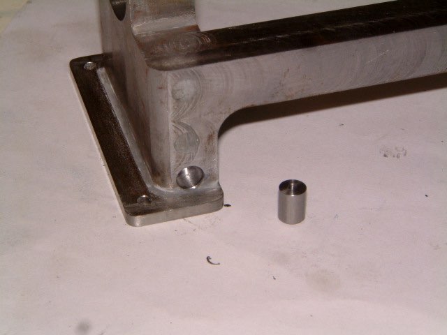
Both parts before being pressed together.
And using the big mill vice to press them together.

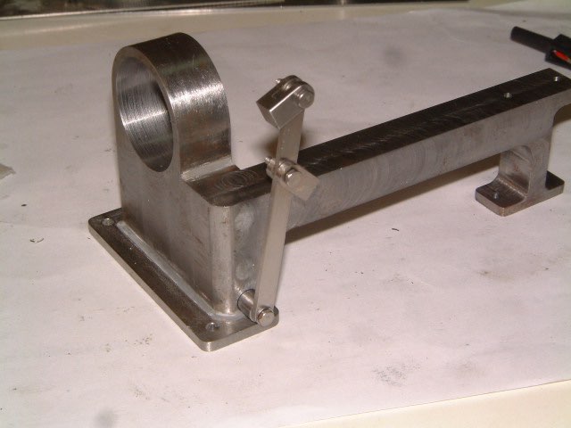
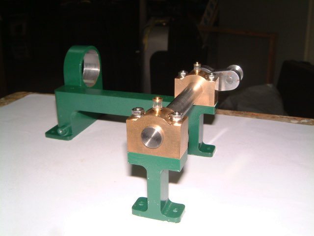
And the whole assembly finally complete with the valve lever fitted to the pivot.
I drilled and tapped both bearings.
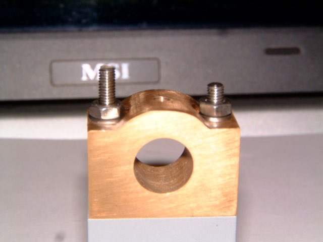
Decided to give the bearing supports a splash of colour.

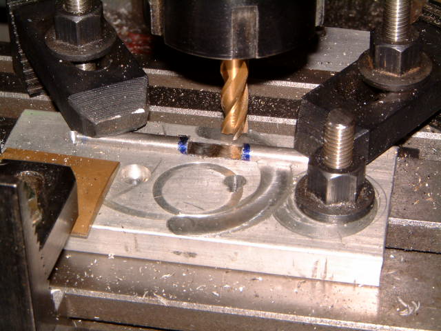
Started work on the valves with four blanks to the appropriate length. Clamped a piece of scrap aluminium flat bar to the mill table, and with a 6mm ball-nose end mill I cut a groove 2.8mm deep.

This was to hold the valve blank in place while milling it.
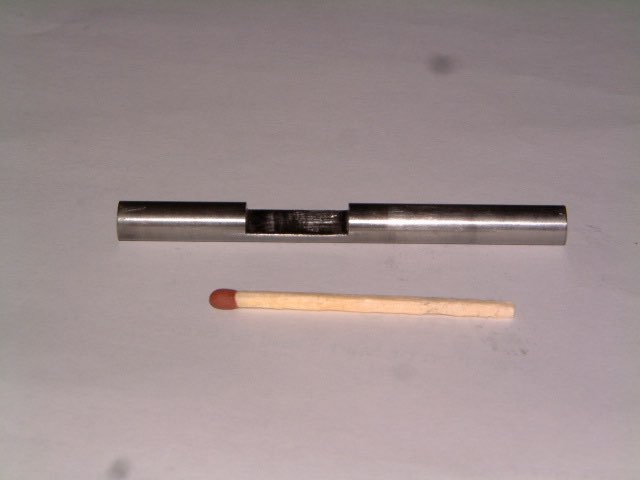
I milled the slot in the valves and then cut a 1mm slot on the backside. This should help in adjusting them with a screwdriver. I also made a light centre punch mark to show me on which side is the milled slot.
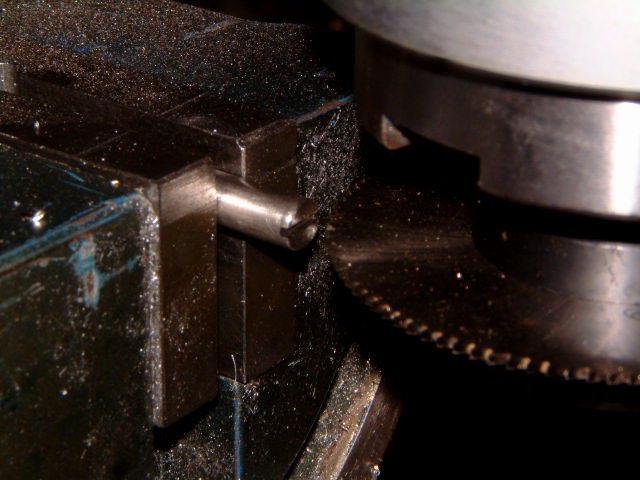
As these valves are a one part construction as opposed to a two part construction as shown on the plans, I turned down the front part of the valves to 3mm.
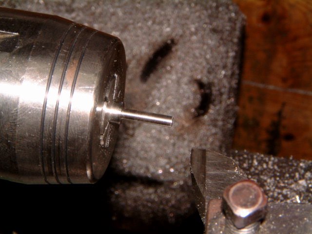
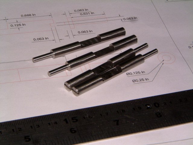
And here are all four valves complete.
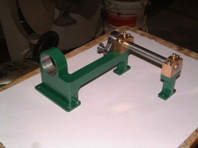
To give me an idea of the size of this model and the base, I assembled all the finished parts together and put them on an A4 sized sheet of paper.


Modelengineeringwebsite.com
the only free and the only weekly magazine for model engineers.
Editor: David Carpenter