MY CORLISS
ENGINE BUILD
Part 20 by Vince Cutajar

MY CORLISS
ENGINE BUILD
Part 20 by Vince Cutajar
For the base I managed to get hold of a piece of aluminium flat bar 8mm thick. It's not as wide as in the plans. It's 200mm wide, a little smaller than 8.5". When I put it on the mill table I realized that I might have some problems cleaning up the sides. It was as big as the mill table!

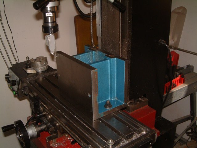
I used a cast iron riser block which was originally meant for a Clarke 3-in-1 lathe. Indicated it on the mill table.
I used a couple of G-Clamps to fix it to the riser block! Cleaned up about three quarters of the top side.
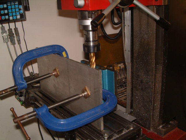
I then slid it sideways and did the rest.
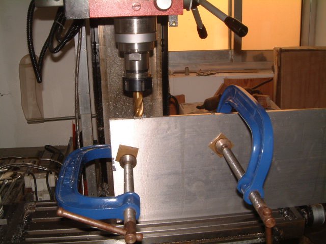
For the two short sides, after a bit of head scratching, it was decided that the best setup for this op was to clamp the plate to the mill table with lots of overhang. I also clamped an angle plate to the mill table.
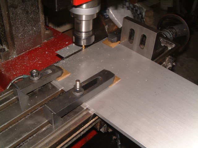
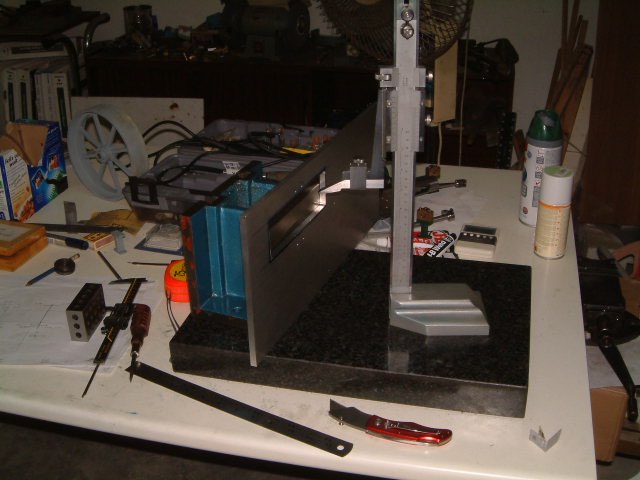
My base is nearly 17" long and I had a feeling that it was too long and would require trimming at a later stage. So, I left the length of the plate longer than plan and see later how much trimming it needs. I next marked the cutout for the flywheel. A little more head scratching and then mounted the plate to the mill table. I used a pair of 1-2-3 blocks as spacers below the plate.
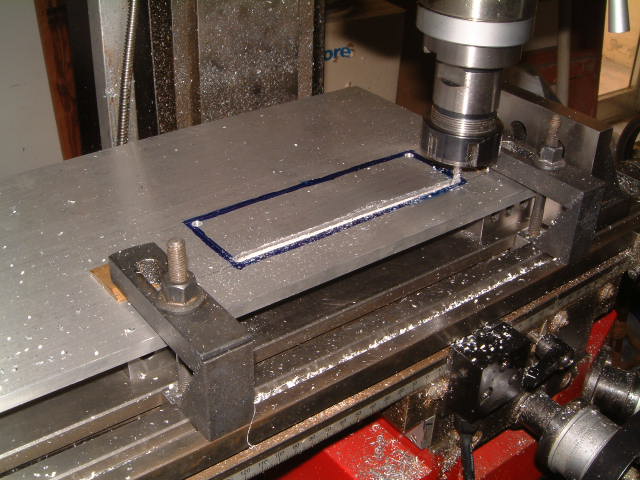
A posed photo of the setup I had used for marking the cutout.
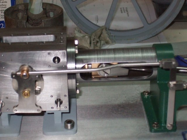
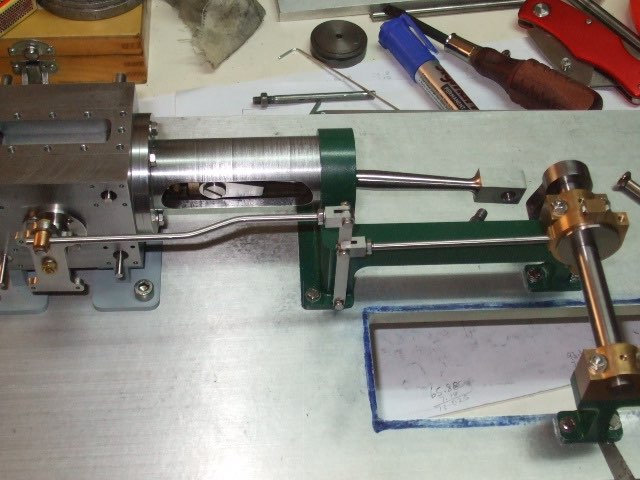
Quickly assembled everything to the base plate so that I could see for the first time how the flywheel will look.

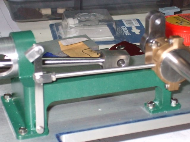
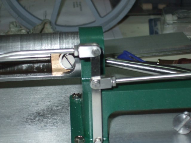
Next I finished up the rods from the eccentric to the lever and from the lever to bell crank on the cylinder block. The nuts behind the forked end of the rods are not really required but I put them there just for looks.


Modelengineeringwebsite.com
the only free and the only weekly magazine for model engineers.
Editor: David Carpenter