DELAGE GRAND PRIX ENGINE PROJECT
Part one by Mike Sayers

DELAGE GRAND PRIX ENGINE PROJECT
Part one by Mike Sayers
Why choose the Delage engine after completing two classic Bentleys?
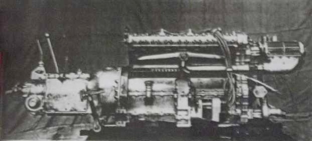
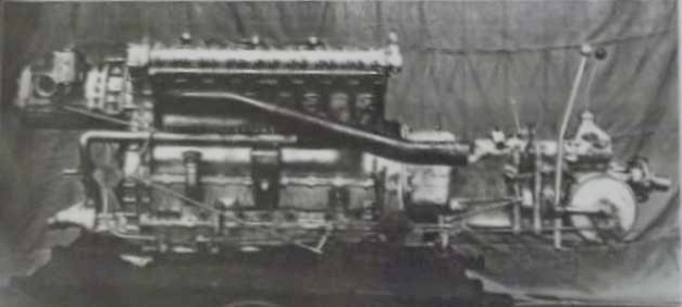
Well, It is a very famous engine. They were built in 1926/27, and they only raced in the Grand Prix in those two years when they won everything. In 1927, they won so many events that the competitors didn’t bother turning up. They were winning as teams as well.
They were only 1500cc engines, but were beautifully engineered and were known as ‘The Swiss Watches’ of Grand Prix engines at the time.

I actually found the original at Goodwood some years ago. The year before, soon after the new Brooklands Museum had opened, the car was presented to them. They tried to compete in a sprint at Brooklands and put a rod through the side. They had the engine out and partially stripped, showing the damage to people, and trying to collect money towards its restoration. With the Blower Bentley almost complete I was looking for a project to follow on and the Delage looked a likely candidate if sufficient information could be found. There was then a series of coincidences.
I was looking at the engine and photographing it when someone tapped me on the shoulder asking me what I was doing. I told him I was interested in the engine and wanted to make a scale model. He said he had bequeathed the car to Brooklands and I should contact Allan Winn the CEO there. As Allan was a member of the Bentley Drivers Club, I rang him up, and he invited me down.
I spent three days in the archives, looking at the drawings. I subsequently met Eddie Beresford who has restored the only car that is absolutely original, which is now in the Collier Collection in the Revs Institute in Naples, Florida. He got to know what I was doing, and told me he would contact me after he came back off holiday. I asked where he was going and he said “Robin Hoods Bay!” He and his wife came over for tea to see the Bentley models, and he offered all his help. Everything had fallen into place!
I was invited back to see the engine at Brooklands, and eventually they gave me permission to dismantle the engine completely so I could measure and photograph all the components individually. My stepson, Paul, came along with me, and we had free reign to get all the details we wanted. They have even offered to take the car off public display and put it in the workshop for me to measure up the chassis details when the time comes. You can’t attempt a project like this without access to reliable detail.


Other people have been very supportive. I wanted details of the carburettor, because Brooklands car does not have the original Cozette carburettor. I was advised to contact the Rev Institute in Florida, as they have records of everything. I e-mailed the library, and within two weeks they had e-mailed me the drawings of the smaller production carburettor. There were only five carburettors made especially for the racing engines, and they were much larger.
Thankfully, the Institute were interested in what I was doing. I asked for some measurements of the carburettor on their car, so I could “scale up” the production dimensions. Two weeks later I received 16 photos. They had taken the carburettor off the car, dismantled it, photographed every part and pencilled in all the dimensions on the photos. And this is a car worth millions! I was asked to send them progress reports of the build and to maintain contact.
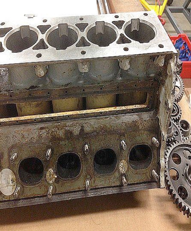
Each full-size piston has a 55.8mm bore. For the model that is 22.32mm. The full-size engine has a 76mm stroke (in the model 30.4mm). The interesting thing about this engine is that in 1927, it had could sustain a constant 7000 rpm throughout a race with a red-line at 8,000 rpm and it ran at that speed regularly. Generally this high rpm was unheard of in other engines of the time.
It has a 9 plate clutch. It is a superb engine. Everything is hardened, ground and runs on ball and roller bearings. There are 62 ball and roller bearings in the engine itself.
Big-End roller bearings are about 7mm. There are 10 rollers on each of the main bearings, 8 rollers on the Big- Ends, and 7 rollers on the camshaft bearings. The rollers run directly on the crank. There isn’t a bearing assembly, it is just a split aluminium cage containing the rollers.
The Rod-Eyes are hardened and ground out as are the Big-Ends. The rollers just fill the gap.
The model scale was dictated by the gears. There are gear drives to camshafts, supercharger drive , magneto, water pump, oil pumps and scavenge pump – 21 gears in total. In full size, these are 2.5 module. Therefore, to avoid the necessity to make special cutters, I decided to make all the gears 1 module which represents 40% scale or 1:2.5 .
The coupling gears on the supercharger are 0.5 module with 48 teeth each and because of the fine clearance between the rotors inside the supercharger the gears need to have virtually no backlash.
I made the first set to standard tooth depth, i.e. 2.25mm x the module number, in this case 0.5, therefore 1.125mm deep. This produced gears with too much backlash. Two further sets were made progressively reducing the depth of cut until a pair of gears ran smoothly with no backlash.
These gears were cut using a standard 0.5 module number 3 milling cutter, cutting one tooth at a time. Very time consuming. I am, therefore, converting my old Shaublin milling machine so that I can generate the gears using a hobbing cutter.
This is a continuous process and, once set and started, will work unattended leaving me free to do other things. For each rotor there is a twin ball race at the drive end, and a single ball race at the other end.
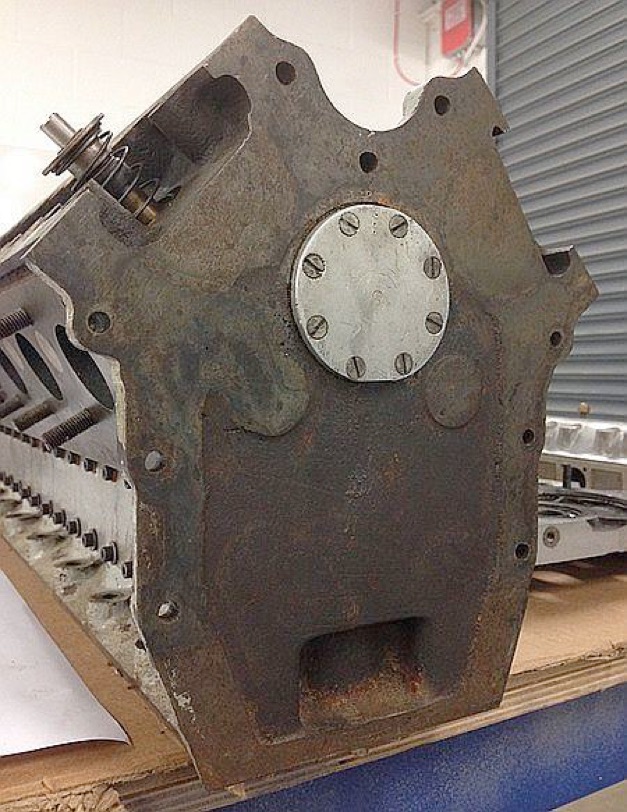
The compression ratio is 8:1 and there’s 10lb of supercharger boost. It ran on a Benzol/Petrol mix. The lubrication system is quite a low-pressure system, almost a ‘jet lubrication’ system. The crank shaft has full circle webs with a V-shaped annular groove around the outer face. Oil is sprayed into these grooves and is flung out by centrifugal force into the Big-End bearings.
There is a row of hatches at the bottom of the engine. These hatches can be removed and there are needle valves which control the oil to each area.
It is a dry sump system using three pumps. One pump supplies oil to the crank and Big-Ends, the second pump supplies oil to the ancillaries such as the cam shaft and timing gears. There is also a ‘scavenging’ pump which pumps the oil back through a filter to the oil tank. All are fitted into a housing in the lower sump.
Cylinders are lubricated by ‘splash’, but not very much. There are plates at the top of the crankcase with just a slot in so the rod can poke through, so it keeps a lot of oil out of the cylinders, it just gets in there as a mist, a bit like the Austin Seven.


Modelengineeringwebsite.com
the only free and the only weekly magazine for model engineers.
Editor: David Carpenter


