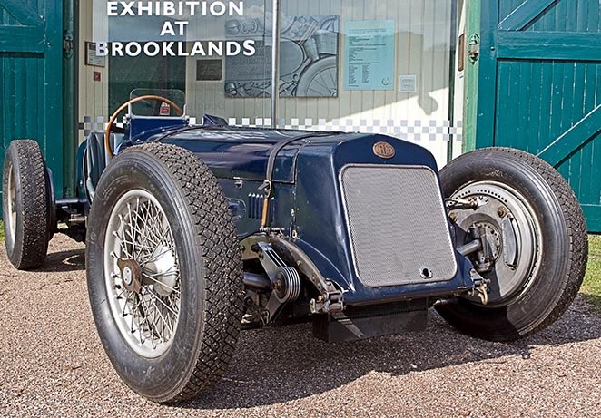
DELAGE GRAND PRIX ENGINE PROJECT
Part three by Mike Sayers

DELAGE GRAND PRIX ENGINE PROJECT
Part three by Mike Sayers


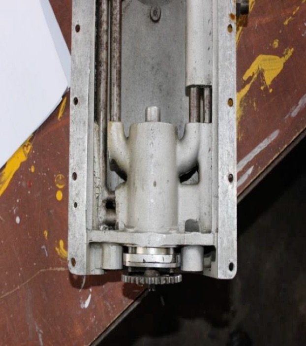
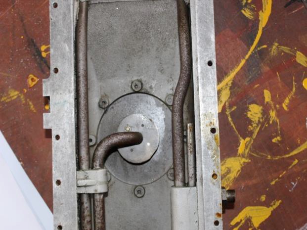
The sump houses three pumps, two pressure and one scavenge, plus two pressure relief valves. One relief valve regulates a low pressure supply to the camshafts, valve gear and all the spur gear drives and is adjustable; the second provides higher pressure oil to the crankshaft bearings. This valve is not adjustable and relies on a fixed length spring to provide the primary regulation.
I spent a tedious couple of days sorting through a large box of assorted springs, testing them on my wife’s kitchen scales, in order to find two of the correct diameter and rate. One was kept as a spare.
This valve also incorporates a camshaft operated by external rod system which will eventually be connected to the throttle linkage. This will provide a higher oil pressure to the bearings when under high acceleration. This is something I have not seen before in other racing engines.
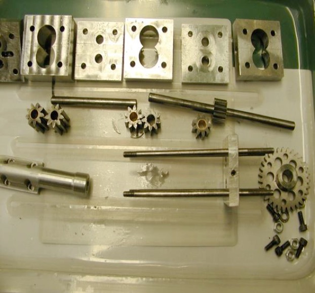
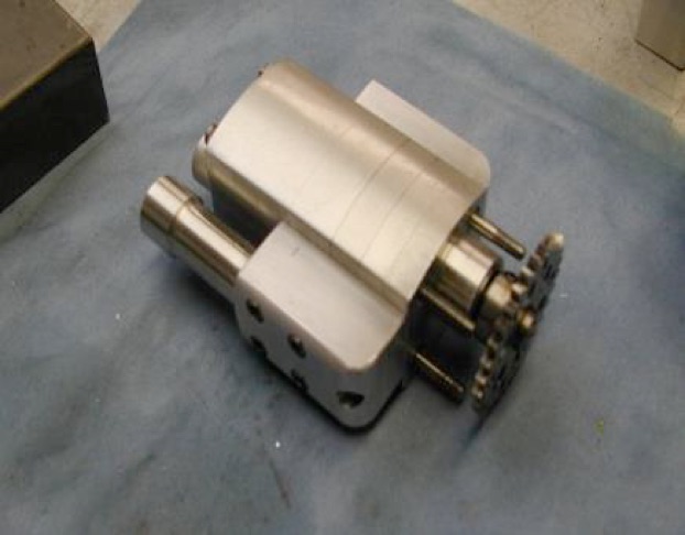
In the full size sump, all the prefabricated steel supply and return oil pipes connecting the pumps to the external flexible hoses, were set in the sand moulds and the molten aluminium poured in around them. The three pumps are a tandem sandwich driven by a common shaft.
The outer diameter of the assembly was taper turned, and the whole was drawn into a matching taper bore in the casting, where all the ports were arranged to match each other. Sadly, there was no way that this could be repeated in the model and the method employed will be perhaps the greatest deviation from the prototype when the model is complete.
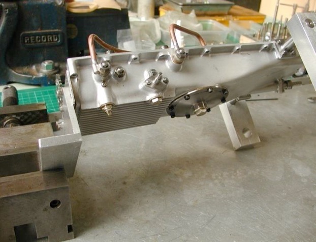
I, therefore, decided to try and test the system.
It was important to be sure that the scavenge pump would clear the total delivery from the two pressure pumps back to the oil tank, otherwise the sump would slowly flood. Also, a trial test would allow the pressure relief valves to be set correctly before trying to run the engine in the far future.
It was also important to ensure that the system would prime itself without external assistance. After final assembly there would be no indication of this problem except no oil pressure, and that could have several causes.
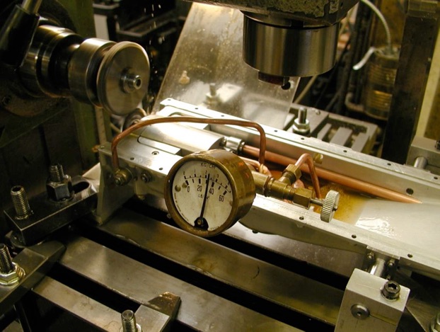
To test these questions, the assembled sump was clamped to the milling machine table, and gear driven from the horizontal arbor. A baked bean can, with copper pipes soldered in top and bottom, served as an oil tank and connected up with neoprene tubes. The mill speed was set to provide a pump speed of 400 rpm, representing its rpm at the engines idle speed, and the bean can/tank filled with SAE30 monograde oil.
After that nothing went to plan!
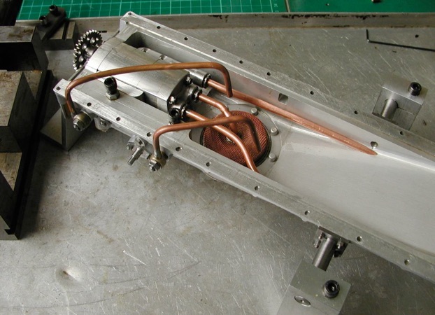
The first thought was that the oil was too thick. Thinning down the oil with WD40 improved things very slightly, but both pumps could not be persuaded to supply together. At higher speeds the flow seemed to reverse in the low pressure pump and appeared to admit air into the suction of the other pump, leading to failure there too.
Two things were suspected. The first that the porting arrangements at the inlet side of the pump bodies was wrong, (confirmed by a reference to a web site on gear pump design), and made worse by the neat little Siamesed manifold connecting the inlets of the two pump inlet ports. Suitable alterations were made to the inlet ports, and a temporary twin inlet manifold made up as an experiment.
The design of the full size sump has only two connections to the oil tank, obviously one in and one out. So the single outlet from the bean can was retained, and a T-piece inserted at different distances from the tank to connect to the two inlets on the trial twin entry manifold. It was found that as long as the Tee was as close to the tank as possible, the system would work at 400 rpm. Any substantial increase in rpm again showed an apparent reversal of flow in one of the pumps, leading to aeration or cavitation in the other, and eventual failure of both.
Here there was a major pause for thought!
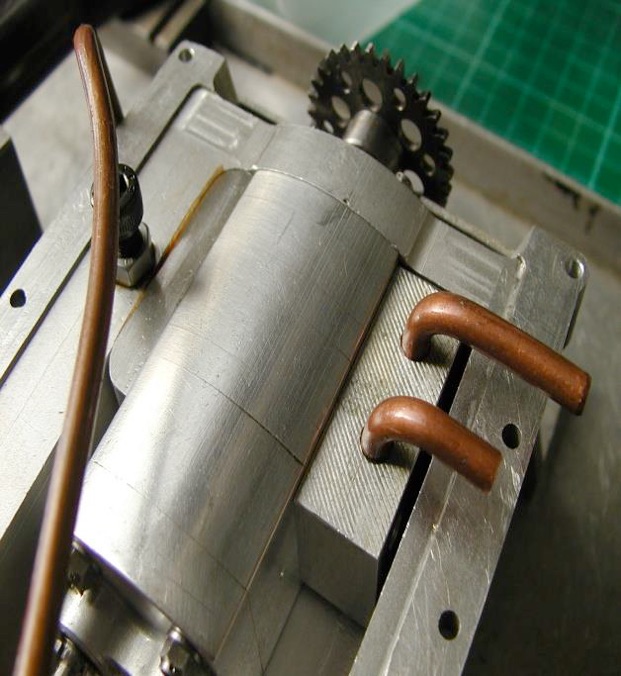
I had expected the scale dimensioned pumps to supply much less, and have a much lower efficiency. The theoretical output of the pumps also seemed much more than would be required, though I had no real idea just how much oil the engine would need.
Using the much acclaimed wet finger approach, a guess at 0.5cc per rev sounded sufficient. New pump bodies were machined up, and the gears shortened and keyed to a new drive shaft and idle shaft. Drastically increasing the size of the internal supply pipe to the pumps appeared to be more difficult than it turned out.
By upping the diameter to 1/4” o.d., and using the thinnest wall tube available, the cross-sectional area of the bore was doubled. A major improvement.
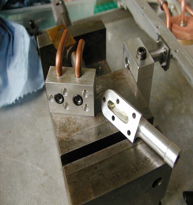
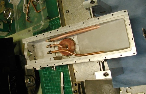
A new inlet manifold was machined up with separate internal ports, and a larger connection to suit the 1/4” diameter supply pipe. The external union connection was also bored out to 1/4” diameter. All this was done without any change to the outside appearance.
As a precaution, the short suction pipe from the base of the sump to the scavenge pump was also replaced with a thin wall tube. By doing this, the clearing rate was increased. Bending this thin wall tube required lead filling.
After all this work, and using Castrol GTX 0-30 motor oil, it was a great relief to find that the next test proved a remarkable success. The pumps primed unaided, and both pressure pumps sustained a full supply at all speeds up to 3000 rpm with no aeration in either delivery. The scavenge pump also cleared the contents back to the tank at all speeds, though the oil was a bit slow flowing through the gauze filter. It is possible that when the oil is hot this might improve, but a wider mesh filter gauze has been fitted just in case.
A manifold with a pressure gauge and needle valve restrictor was fitted to the high-pressure pump outlet again, discharging into the open sump. While running the system at various speeds, the restricting valve was closed to check that the relief valve could pass full discharge without the pressure rising to astronomic levels.
Thankfully it regulated oil pressure to 20psi at idle speed, and 45psi at higher rpm. All that messing about with springs was worthwhile. Operating the throttle operated cam lifted the available pressure to 60psi. About as good as could be expected, though it is very unlikely that this pressure increase will be required. I am pleased to have built it into the model, and even more pleased to find that it works.
The pressure gauge etc. was then connected to the low pressure pump outlet, and adjustments made to the spring loading. This gave 10 psi, and again the output was closed off to check that the valve could pass full pump output.
Part one here. Part two here. Part three here. Part four here.




Modelengineeringwebsite.com
the only free and the only weekly magazine for model engineers.
Editor: David Carpenter