DIGITAL LINEAR SCALES
Graham Fry


DIGITAL LINEAR SCALES
Graham Fry

Several years ago, after a few errors caused by either ‘backlash’ or my miscounting hand wheel revolutions when plotting hole position or milling on my Warco Minor Mill/Drill, I decided to improve accuracy by fitting digital linear scales. These easy-to-read simple scales are very similar to the digital vernier scales we have all used over recent years. They are low cost and usually powered by a small LR44 battery.
At the time, scales were only available with direct readout so I chose to fit them to the “Z” (vertical) axis and the “X” (longitudinal) axis only. Although the “Y” (cross) axis was equally important a direct readout scale here would have been very difficult to read so this was abandoned at the time.
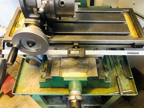
Z-axis scale.
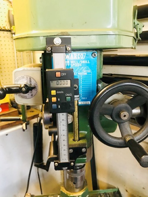
X-axis scale.
Recently, while browsing options to fit a full three axis DRO to my lathe, I came across digital scales available with remote readout. Just what’s needed to complete the set up on my Mill/Drill, I thought. So, I ordered what I thought to be the correct size from Machine-DRO. Two days later it arrived and I offered it up prior to fitting.
Bit longer than I thought, the size of 300mm is the actual readable scale, not the overall length. Should I re-order a smaller size (next one down a bit too short) or is it possible to cut to size? After a bit of research, I decided to take the gamble and cut to the exact size I needed, so after scoring the magnetic tape with a craft knife, I turned it over and cut the aluminium rail with a junior hack saw. Did it still work OK? Yes, absolutely fine.
Now I needed to fit it to my machine. As we were again in lockdown, the scrap box was raided and my supplies of nuts, bolts and “that will come in useful one day” came up with all I needed to fabricate and fit.
.
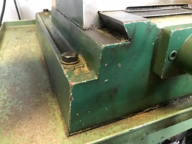
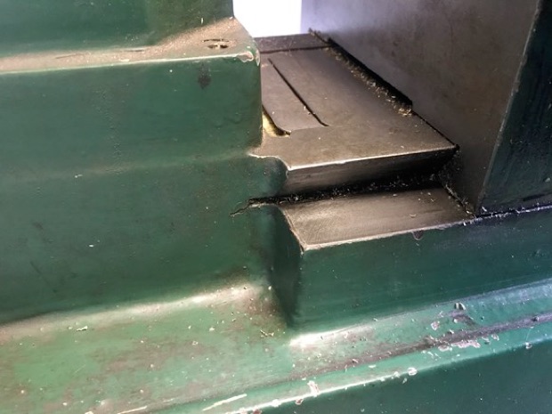
Fixing points chosen, I set about fabricating the fixing brackets. This is where it is easy to make an error without thinking it through thoroughly. The rear bracket is an aluminium block milled to the contours of the pillar base casting and held in place by two M6 cap screws. I like to position bolt holes evenly so things look right, if only I had put the centres a little closer together.
When I offered it up… how on earth was I going to drill and tap the bottom hole? If only I had positioned it a bit higher it would have been easy-peasy. As it was after an hour-and-a-half and a lot of muttered comments I had the hole drilled and tapped, so think twice is always the better option.
.
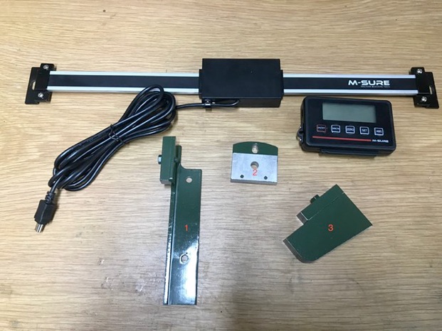
The parts I made are shown above are from left to right 1) The front bracket, this a scrap of 1’ x1’ aluminium angle with a spacing pad. It is important that you have a means of ensuring the scale is parallel to both the cross slide and the base. Here the spacing pads can be measured and milled to the correct thickness. To ensure the scale is parallel in the other vertical plain it has slotted holes at each end. Finally, to ensure that it is true in both plains, a DTI is used for final adjustment.
2) This bracket attaches to the rear of the Reader head with two M3 mushroom head cap screws and to the cross-slide casting with a single M5 cap head screw.
Again, the fixing hole must be slotted to allow for adjustment.
3) A scrap of 625” thick aluminium is the material used here to construct the rear bracket. It is shaped to fit the casting (if only I had made the bottom hole 3/16” higher!) Again, a small spacing block is added to ensure that it can be adjusted to be parallel with the cross slide.

.
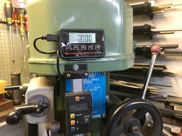
Finally, the display screen is connected to the reader head by a cable (approx. 2m). The screen has magnetic pads which I have used until I am sure it is in the right place. It also comes with a mounting bracket which it clips into for a more permanent fixing.
All that remains now is the question - shall I fit full DRO to my lathe?






Modelengineeringwebsite.com
the only free and the only weekly magazine for model engineers.
Editor: David Carpenter