JESSOP & APPLEBY STEAM CRANE PROJECT
By Tony Sprent

JESSOP & APPLEBY STEAM CRANE PROJECT
By Tony Sprent


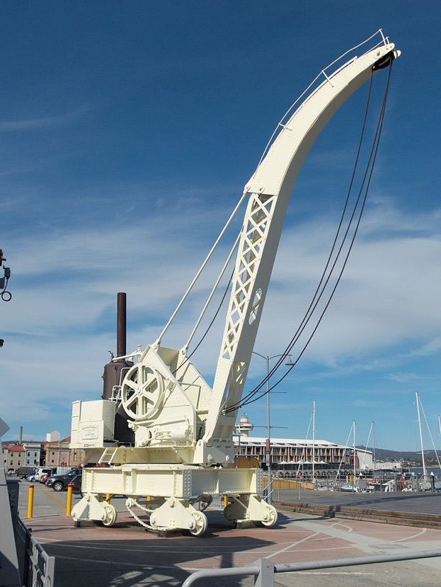
The Jessop and Appleby Steam Crane has been a landmark at Constitution Dock in Hobart for the last 120 years. Constructed by Jessop and Appleby of Leicester UK, it was purchased by the Hobart Marine Board in 1897 and arrived in Hobart in 1899. The total cost was 2662 pounds, 15 shillings and 8 pence. The crane had a working capacity of 25 tons at a fixed radius of 30 feet and designed to travel on rails parallel to the wharf. Powered by steam supplied through compression coils from a wood fired boiler, it could turn through a full 360 degrees.
The crane was mainly used for loading apples for export, once a major Tasmanian industry and for lifting boilers, engines and other heavy loads. It was used extensively until the 1960s when the boiler was no longer inspected.
The crane appears in many historical photographs including one taken at the end of the Boer War with many people climbing up the superstructure to get a better view of the returning troops. After it was decommissioned, it was set up at the entrance to Constitution Dock, made famous by arriving boats in the Sydney to Hobart Yacht Race. It has been reasonably well conserved but there is considerable evidence of rusting and deformation due to water penetrating between the plates and panels. It is painted a rather boring off-white colour which at least is protecting it. I have no idea what the original colour was.
For many years I have been interested in the old crane and it has long been an ambition of mine to build a working model. I am not a model builder but have fairly extensive metal working experience designing and making various components for the University of Tasmania’s various radio and optical telescopes as well as other projects. I was able to get hold of copies of the original Jessop and Appleby design drawings which gave details including dimensions of the main components and structure of the crane.
I decided to use a scale of 1:12.7 or 2mm to the inch. Since all my work and tooling is metric, I wanted a simple conversion from the original drawings. This gives a model about 800mm by 350mm with a height of 1200mm. Fairly large!
I realised I would need a boiler design and found the drawings of a 75mm diameter vertical boiler produced by Julius de Waal. I’d seen many of his drawings at various times on the Internet and I wrote to him asking his advice as to whether I could scale his drawing up to suit the crane model. Julius wrote back to me saying that if I could send him the original drawings and photos, he would make a set of scale drawings of every part. It was at that stage I decided that I would have to make a model!
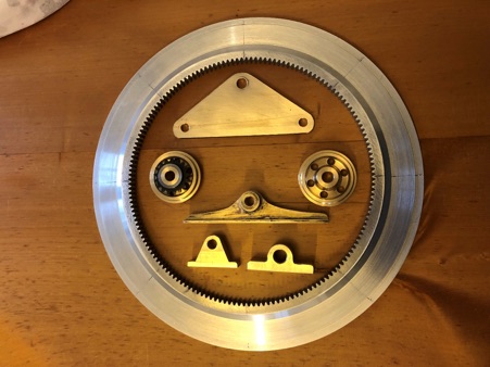
As I am 78, I decided that rather than making an absolutely correct detailed and scaled model which I might never finish, I would cut corners with such components as gears and purchase these off the shelf where possible as close in scale as possible to the original but using standard metric gear sizes. The gears are mainly 1.5 modulus with a couple of 1 modulus pairs. I have been able to purchase all the required gears from China at reasonable cost. These are all solid gears which I will modify where necessary by machining spokes and flanges to resemble the original gears. I won’t be using rivets. Trying to source materials for construction is almost impossible in Tasmania. Freight and postage are expensive and getting components can take ages. I have a fairly large stock of various aluminium, brass and steel sections left over from the various projects I have made in the past. I have been lucky to acquire several sheets of 0.9mm,1.2mm and 1.6mm brass when one of the workshops at my university closed down. These materials will be my mainstay for construction. Where dimensions don’t matter, I will be modifying Julius’s drawings to suit my stock. Thus, for example, the main shaft between the lower carriage and the upper structure will be 23mm rather than 25mm diameter. The large ring gear shown is made from 12mm 6061 aluminium plate. At a cost of a dozen cans of Cascade Lager I was able to get the teeth waterjet cut in a workshop here in Hobart. This saved a huge amount of time as cutting this in my workshop would have been a difficult process. I finished the outside rim in my workshop. I still have to cut the mounting lugs which I will do when the main carriage is complete. The ½” chain sprockets are commercially available on the internet. The central drive shaft bearing is my first effort at silver soldering which needs cleaning up. So far, I have made all the wheels, wheel carriage plates and bearing blocks. I am working on the main part of the undercarriage currently.
I would be very pleased if anyone else decides to take on building a similar model and would love to hear from anyone interested in the crane and/or model. I have the original drawings as PDFs and am happy to send them. I also have many detailed photos, particularly of all the gears and other parts. If anyone would like these, please let me know.
I can be contacted here.





Modelengineeringwebsite.com
the only free and the only weekly magazine for model engineers.
Editor: David Carpenter