HOW TO MAKE
MINIATURE SPARK PLUGS
Part two
By Graham Meek

HOW TO MAKE
MINIATURE SPARK PLUGS
Part two
By Graham Meek

Having the luxury of a smaller lathe I then held on the short portion that was turned first and supported the just turned 1.5mm diameter with a running centre in the 1mm diameter hole. While this may be frowned upon, as this is not the correct way to support the work i.e. there is no 60° cone for the centre to locate on, but it does work. Should there be any slight wear or deformation of the hole then this will not matter as later this will be spread with a 90° punch when the electrode termination is fitted.
The PTFE insulator was turned next, producing the 4.8mm diameter by 10.2mm and also at the same setting the 7mm diameter for a length of at least 18mm. The 1.5mm hole can be partly drilled through at this setting, which will ensure all is concentric at this end. Again the detail is parted off over length by a similar amount, and then held in a chuck etc. By placing the shoulder that forms the 7mm diameter against the face of the chuck jaws, collet or split bush it is possible to relocate the part length ways which will prove useful later on.
A useful tip if using a chuck for this operation, I usually put a ‘dot’ with a felt tip pen between the jaws adjacent the ‘preferred’ chuck key socket, that way I can always return the work to exactly the same place and ensure concentricity. The 4mm diameter by 3mm long portion can now be turned; you will notice that there is a 120° angle specified. A special chamfering tool was made to turn and form this all in one go.
The 1.5mm hole through the insulator is completed and using a sharp 2.5mm slot drill the counter bore is put in accurately to 2mm deep. Remove from the chucking medium and try a dummy assembly with the electrode in place into the plug body to see if the end of the electrode is flush with the end of the earth electrode on the body, or in the case of the single electrode that there is a 0.5mm spark gap. If it does not protrude through far enough, remount in the chucking medium and using the chamfering tool extend the 3mm dimension by the amount that the electrode is below the earth electrode, reassemble and see if your rectification is correct.
I would not worry about an error of approximately 0.1mm either way. Now try it with the Fish Spine in place, if the electrode is now short again then material now needs to come off the face of the insulator around the 2.5mm counter bore. Be sure to remove the centre electrode when doing this operation, once again re-check to see if your reworking is correct.
The plug termination piece is made again from brass. The radius on the end is not critical but a small radius form tool takes minutes to make from a piece of Ground Flat Stock or Gauge Plate using the side of an 8.5mm diameter end mill and the material held at an angle in the vice of about 12° to the horizontal. I tend not to temper these small tools after hardening; maximum hardness is assured and the risk of breaking due to ‘brittleness’ extremely small.
After parting off ensure that the under face that goes against the PTFE insulator is flat, the best way to ensure this is to sharpen the parting tool before commencing the manufacture of this part, brass is a very particular material. If the face is not flat place the termination on some 600 grit ‘wet or dry’ paper on a flat surface using your index finger to apply modest pressure and your other hand to hold the wet or dry, move the part in a figure of 8, checking from time to time on progress.

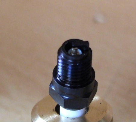
Insert electrode into the insulator; mount the two parts into the brass anvil you have just made; place on the brass terminal and, using the 90° punch located in the 1mm diameter hole, give the punch a light tap with a light hammer. Check to see if the terminal is loose by trying to rotate the terminal, if it is loose then give it another tap with the hammer and punch, a photograph of the set up is included.

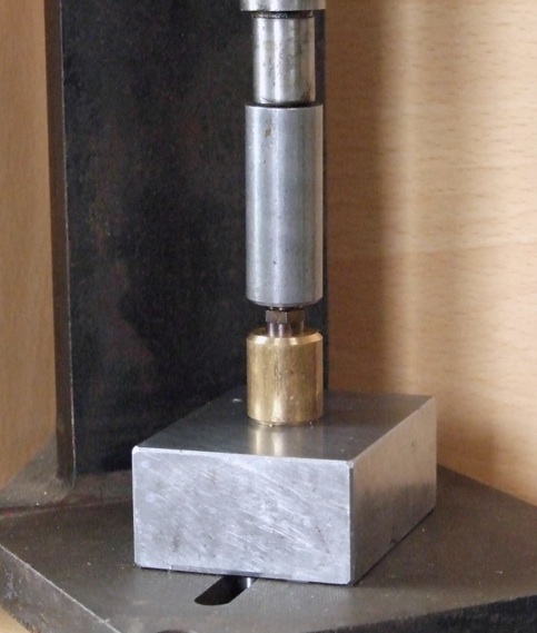
This last piece in conjunction with the brass support is used to swage over the plug body, while I have an extremely small arbor press for this I am sure that given the forces involved a drill press could be pressed into service for this. I would not recommend, on any account, the use of a lathe. I have seen this procedure shown in other publications and I am appalled every time I see it.
While it is possible to swage the items with the use of a hammer, you miss the feel of the arbor press as the BMS yields and closes the joint. A hammer blow is just that, and always leaves one wondering was one blow enough, perhaps I should give it another? It is after this second blow that you remove the plug from the brass support and wonder what the traces of ceramic are doing on the surface of your ‘anvil’ and how come bits of my plug’s ceramic insulator are missing. A photograph shows my particular set-up.

The sealing washer can be made from copper or aluminium, in both cases the washers will need to be annealed. It is a good idea to make a batch of the washers just in case you need one in a hurry. A small un-threaded portion has been purposely left on the plug so that the washer has a positive location at the plug sealing face.
Looking at many of the commercial caps on the market they all look very bulky for the size of the plug. I therefore decided to design my own cap; many designs were evaluated before I settled on the design presented here. They are extremely easy to manufacture and changing or checking a plug is no more difficult than in full size practice. I have included a drawing of the Plug Cap and a photograph.
A few notes on the construction might not go amiss. The main part of the cap was turned from black Delrin, on the outside diameter, the radius on the end was put on using a form tool constructed in the same manner as above for the terminal. It is not essential for this radius to be there again it is down to personal preference. I have always felt it is nice to change things here and there; it sort of puts your own stamp on the job.
Part-off the cap slightly over-size on length, mount in the chuck and face off to overall length. In the machine vice, drill and ream the flat-bottomed cross-hole for the cable entry piece. Using this hole as a gauge turn up the cable entry portion of the cap such that it is a good press fit into the cap main body, also put in the 4mm diameter hole for the cable and the 2.5mm diameter clearance hole for the wire, which goes all the way through.
Assemble the two parts together returning the assembly to the lathe chuck with the cable entry portion between two jaws and machine the internal profile 5mm diameter, again flat bottomed by 10.75mm deep, (a slot drill will do this job adequately after first drilling the hole).
The brass clip that goes over the terminal piece requires a little explanation, in that the hole in the clip wants to be the same size as the terminal in order to get a good grip on the terminal. I use a small boring tool made from a broken end mill or slot drill shank. It is ground along the lines of a tool shown in Photo 147, page 224 of George H Thomas’ The Model Engineers Workshop Manual. With this tool I can plunge straight in to depth slightly undersize on diameter, finishing to size using the end of a drill shank to gauge the size of the finished hole. Because the tool is ground square on the end it automatically flat bottom’s the hole.
Before parting off transfer to the machine vice with the stock resting on a parallel to ensure squareness to drill the cross hole and with the turned portion over hanging the end of the vice. Drill through the cross-hole, the size of the cross-hole depends on the size of the wire you are using. In my case after tinning the wire it was 2mm diameter, the wire in question in this instance was a replacement voltmeter cable, again available from RS.
With a slitting saw produce the slit down to the depth of the flat bottom. If you now mount the rod vertically in the milling machine, (use a V-block to locate it vertically), with the drilled hole parallel to the table movement, sighting along a drill in the cross-hole and lining it up with the edge of the table is plenty good enough, but you can ‘clock’ the drill shank if you prefer. Using the same slitting saw produce the two horizontal slits to form the clip.
Place back in the lathe chuck and part off to length, check the fit of the terminal on the clip and if it is thought to be too slack then with small long nosed pliers lightly turn in the ends of the clips. A drill in the cross-hole makes for easy removal of the clip if the fit is too good and you get the part jammed on.
Insert the cable through the cable entry point so that you can see that the tinned end is fully into the cap, using a piece of masking tape mark the junction of cable and cap, remove the cable. Put the clip in the cap and align the cross-hole with the cable entry hole, a slightly smaller drill than the cross-hole is helpful in aligning the clip. Insert the cable ensuring that the cable goes right home, with the cap vertical and the radius end resting on a piece of softwood. Using a sharp centre punch make an indentation or two in the flat bottom of the clip in line with the cross-hole. Very gingerly check the security of the cable by pulling the cable, the masking tape being a dead give away to any movement. If you are satisfied, the project is finished. If not, a couple of more blows with the hammer will cure it.
Although to date I have not evaluated the idea it should be feasible to manufacture the 10mm plugs using a slightly larger Fish Spine. My own passion is for miniature plugs and I am hoping to produce similar plugs in 4.5mm thread size in the future. However that will have to wait, as the next project is a 10cc diesel engine, with working injector and injector pump.
MEWS IS SPONSORED BY - BRISTOL EXHIBITION - HARROGATE EXHIBITION - TEE PUBLISHING - MERIDIENNE EXHIBITIONS - LYNX MODELS - CAMDEN MINIATURE STEAM - TRANSWAVE CONVERTERS - MESSE SINSHEIM - CHRONOS - PAULTHECAD.CO.UK - ECCENTRIC ENGINEERING - WARCO -
MODEL ENGINEERING
MODEL ENGINEERS
MODEL ENGINEERING WEEKLY WEB MAGAZINE
MODELS TO BUILD
GREAT MODELS
TOOLS FOR MODEL ENGINEERS
MODEL ENGINEERING FOR BEGINNERS
MYFORD