Graham Corry of Alyn Foundry & Sons has reintroduced castings for the popular RLE design of hit and miss engines. alynfoundry103@gmail.com.
This is the first engine to be built to a new set of drawings which are in metric and which will hopefully attract newcomers into the hobby who have been brought up with the metric system and have tooling and machines based on that system rather than bananas.
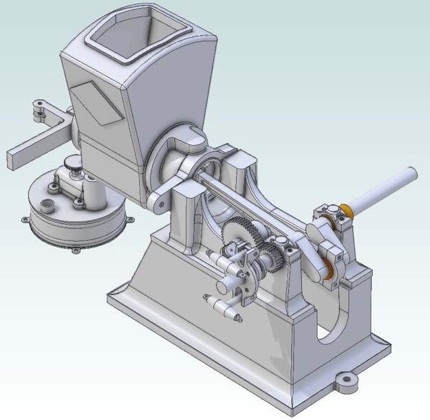
The new drawings include a newer carb design and show modified rocker arm, rocker bracket, cam and head details to suit its straight vertical pipe entry. It will show the MOD gears; metric fixings; O-ring for the piston, and a fuel tank, as well as optional square push rod and governor balance weight designs.
Lastly, there will be details of a cart with, hopefully, the addition of cast cart wheels and axle brackets and a spoke mounted pulley casting that will be available as extras.
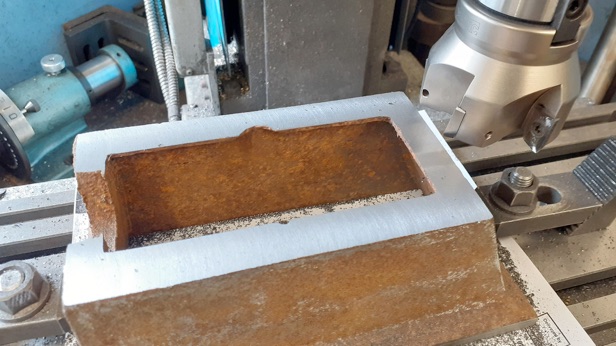
Starting with the base casting after a light fettling it was shimmed up on the mill table to get the sides tapering equally and the bottom flange milled flat using an insert face mill. While still held in position by the two clamps on the inside a round disc was held in the mill spindle to help best locate the centre of the two cast bosses.
After spotting and drilling for the hold down holes I ran around the edge to just clean up the flange so it was straight enough to use as a reference surface, you may also be able to see that I have milled the internal fillets to the left boss stopping at a scribed line that was done around the disc at the time of locating it which can be used as a guide to trim the bosses to a more attractive shape.
Now that the base had a flat bottom it could be clamped to the mill table, the skimmed flange edge set true and the upper surface machined again with the face mill. You may notice I am using polished inserts intended for aluminium and non ferrous on this cast iron part as I find the sharper inserts put a lot less strain on the lower powered and less rigid bench top mills than the standard inserts do. The carbide will also cope a lot better should there be any hard areas in the castings (not a problem with these specially coated Welsh products).
I left out drilling and tapping the four holes to mount the crankcase until I had machined that, but they could be put in now working to the sizes on the new drawing. A bit more fettling of the surfaces and clean up of the corners was done as well as spot facing the two mounting bosses before moving on to the next part.
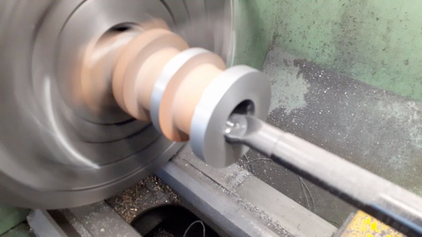
The cylinder casting was given a light fettle so I could take a few measurements and have reasonable surfaces to hold before being put into the 3-jaw and set so the three ‘rings’ ran as true as possible. I then took a couple of light passes across the end to clean remove the draft angle and leave a clean surface. While in the chuck I also just cleaned up the middle ring to give me something to clock true and also run a steady on if I felt the need for one.
I've seen a lot of people use the 4-jaw and a steady to do the boring of the cylinder but I opted to clamp the freshly machined end to the faceplate, tapping the casting until the central ring ran true. The end was cleaned up both on the face and OD and then I used a 16mm boring bar with CCGT insert to bore to the required 33mm.
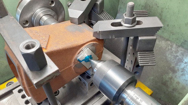
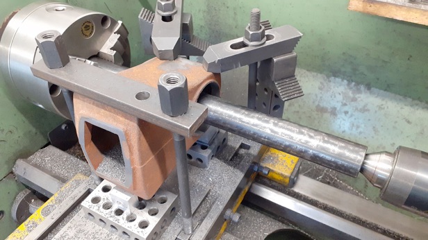
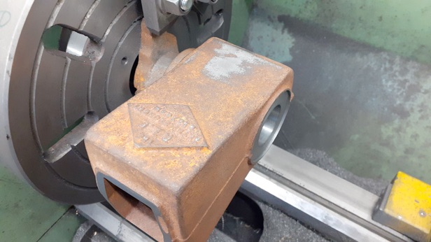
I did not do any more work on the cylinder but left it fixed to the faceplate while I made a start on the hopper. Again after a bit of a fettle and some measuring up I hot glued a couple of pieces of scrap aluminium to each end and marked out the centre of the bosses. The casting was then packed up and clamped to the lathe's cross slide and the position adjusted so the marks lined up with head and tailstock centres. I find this type of setup preferable to having an unbalanced lump in the 4-jaw and the between centres boring bar that will be used does not flex as much as a toolpost mounted one can do so you get a straighter bore. Not the ideal clamp positions but it was solid enough.
Initial cuts to enlarge the cored hole were done with a boring head. Then I switched a 28mm between centres boring bar, held between chuck and tailstock bar to take the hopper ends out to the required 54mm dia. Once this had been done I changed to a tool with its cutting edge at 90deg to the bar's axis to face off the boss that will face towards the crank.
Now that I had a known bore I used the hopper as a gauge to get the final size of the cylinder, seems about right as it stays horizontal without swinging down but can be pushed on by hand.
I left bonding the two together until a bit more work had been done.
Quick video of some of the operations described above.
PART TWO HERE


