
Before machining the main crankcase casting of the RLE it is worth getting the bearing caps ready. These are supplied as a single piece. After a skim cut to flatten the bottom, and then the ends with the now flat bottom against the vice fixed jaw, the casting can be cut in two. Well, actually, you can cut it into three as there is plenty of length and it's quicker to saw away a waste piece than turn it into chips.
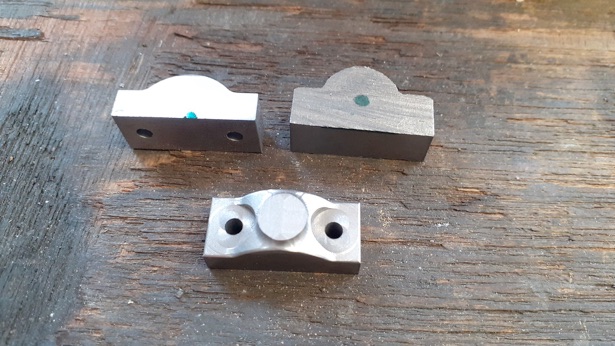
I could see how Graham made the pattern many moons ago simply by gluing a piece of half round timber moulding onto a flat piece and adding a bit of draft around the edges. This gives the profile shown top right in the following photo and if we assume the radius of the "hump" is where the green sharpie mark is then most of the material needs to come off the bottom which combined with a bit of flattening of the hump results in the section shown top left. I went a bit further and used the excess height of the hump to provide enough material to form a boss that can later be drilled and tapped for an oil pot - middle bottom. Clearance holes can be drilled and spot faced so the caps are ready for when they are needed.
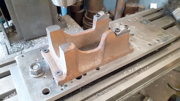
The crankcase was shimmed up on the mill table to get it to sit nice and level without being distorted by clamping pressure and the face mill used to flatten its bottom. Now that I had a solid surface it could be set up on the table with some parallel packing below and set to get the best centre line of the casting in line with the mill's X-axis. I started out by locating the four hold-down bolt holes so they sat reasonably central to the cast bosses noting their positions on the DRO before spot facing to give the nuts a good surface to tighten down onto.

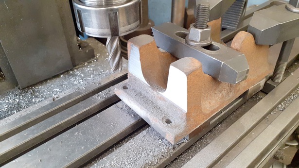
Next the vertical face that the cylinder flange mates to was squared up, just taking off the bare minimum at the top and down low enough that the flange clears the step left by machining away the draft angle. I later blended that small step in to leave a smooth fillet where the vertical meets the horizontal as I'm fussy like that...
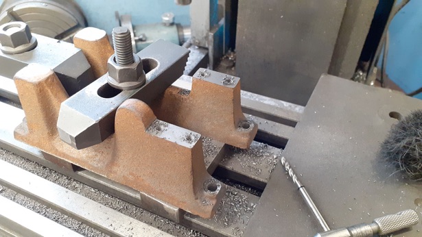
Moving to the other end of the casting the bearing split line was milled down to the required 41mm above the bottom of the base and the stud holes drilled and tapped M4. You can see in the photo that I'm using a spiral flute tap, I've almost gone over to these exclusively as they cut well, clean out the swarf as they go and it means you only need to tap once not two or three times as you do with the usual set of three taps.
For the following operations I like to use a machining plate as it gives good flat surfaces that you can run a DTI against when setting up the irregular shaped casting and also gives a good surface to clamp down.
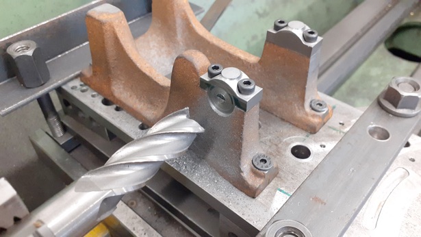
Here I have clocked the long edge of my well used machining plate true along the mill's X-axis, located that edge and established my centre line a known distance from it (50mm in this case) and then using the previously noted DRO positions drilled and tapped so the casting can be screwed to the plate. The bearing caps were then screwed into place ready for boring.
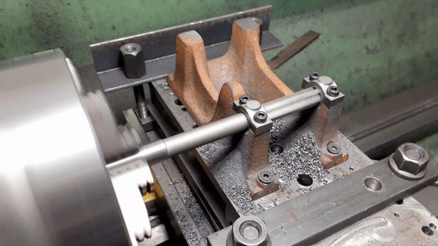
Knowing the exact lathe centre height above my cross slide, and the thickness of the plate, it was simple to work out how much packing was needed to bring the bearing split line up to centre height, clock the edge of the plate true across the lathe and then start machining. First, I used a 16mm 4-flute cutter to produce a flat edge by machining away the draft on the base and stopping just as the cutter touched the bearing cap. I followed up with a 6mm centre cutting 3-flute cutter to remove the pip left by the conventional non centre cutting end mill.
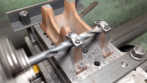
This flat surface could then be spot drilled followed by a 6mm stub drill and then the far end was done with long series centre and 6mm drills. Following that a spot facer I had made for a previous engine was used to flatten the remaining three faces.
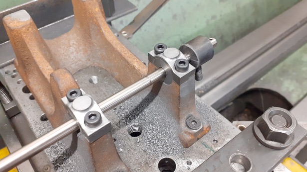
I could then drill out 10mm followed by reaming size for 12mm. If you want to take the option of having the crankshaft run in the cast iron then just drill to 9.7mm and then ream 10mm
A machine reamer was used to finish the holes to 12mm ready to accept the bearings.