Continued from part two here.
While the crankcase was still mounted to the machining plate I clocked it vertical on the mill, located centre and cylinder height and then off set each side to drill and tap for the two studs to hold the cylinder in place.
Once I knew the centre to centre distance of these holes I did the clearance ones in the cylinder's flange. When it was in the lathe I had scribed a horizontal line at mid point across the flange. Here I have clamped a parallel to that scribed line and clocked it true along the X-axis, located centre of bore and then offset each side to drill the holes.
While held like this I used a smaller homemade reverse spot facing tool to machine a nice surface for the nuts to sit on.
Using the heads of a couple of cap head screws poked into the holes and resting them on a parallel the cylinder could be clamped horizontal to an angle plate to flatten the area around the lubricator hole which was also drilled and tapped.
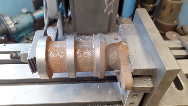
Next was to bond the hopper onto the cylinder, I opted for high temp Loctite 648 on the cylindrical surfaces and a small amount of JB Weld on the radial step towards the crank end of the hopper. To make sure the hopper was sitting upright I mounted the crankcase to the base and the cylinder to the case, a couple of stops in a tee slot set the base true along the X-axis and then an edge finder between the two bearing caps set the engine’s centre line in Y. You may just be able to see at the top edge of the image towards the right hand side a pointer in the mill spindle, this was lined up with the central parting line of the hopper so all was centred up and left to set.
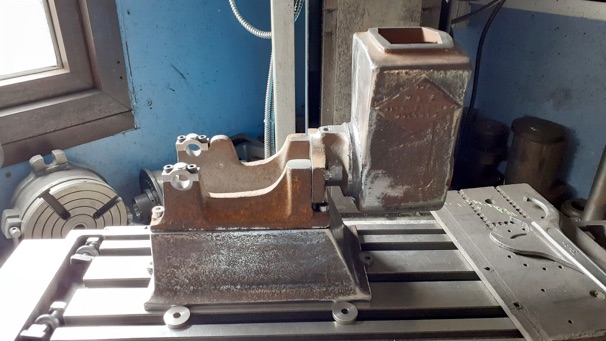
After a couple of days the hopper and cylinder were machined to final length at the head end. Quite happy with the joint which can barely be seen.