BUILDING AN RMC TYPE ‘B’ ENGINE
Part two by Jason Ballamy



BUILDING AN RMC TYPE ‘B’ ENGINE
Part two by Jason Ballamy


The square steps are a bit easier to workout the coordinates for and I find less likely to be deflected sideways, different for those using CNC. But the 2mm round tip does usually live in my holder rather than the square one, I use it a lot when making ‘castings’ as it leaves a nice fillet in the internal corners, also good for small con rods etc. That is also what I used for the 1/4 and half circle concave cuts on the collet end of the carb body. Also have a 1mm one for my Nikole holder for really small stuff, although often a 0.4mm corner radius insert tip will do.
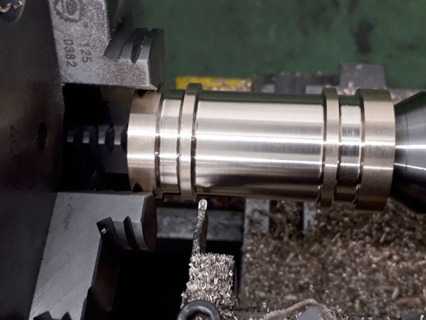
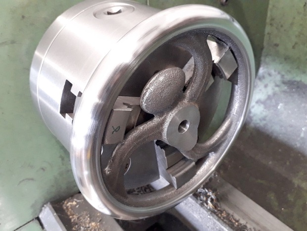
I was just able to fit the jaws of the 3-jaw chuck between the spokes and counter weight of the flywheel casting which ran reasonably true and this enabled me to work on both sides and the edge all at once. The curved finished surface extends around about 220 degrees around the rim before stepping in slightly to the rest of the cast surface. I started by just taking off enough from front, back and edge to get a cleaned up ring and then measured the width. Armed with this size I worked out co-ordinates and machined the rim in 20 thou steps before blending these together with graver; files, and finally some emery.
I also took a light cut to define where the machined surface meets the cast and later blended that in with the Dremel. The hub was also machined, drilled and finish bored to a firm push fit on the PGMS that I used for the shaft.
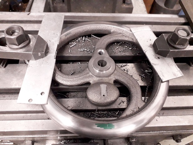
The flywheel was then clamped to the mill table to have the crankpin hole drilled and reamed as well as a slot milled for the governor bracket and a tapped hole to hole said bracket in place. You may also just be able to see the mark on the rim to indicate where the governor pin hole needs to be drilled which was marked with a carbide point held in the mill chuck.
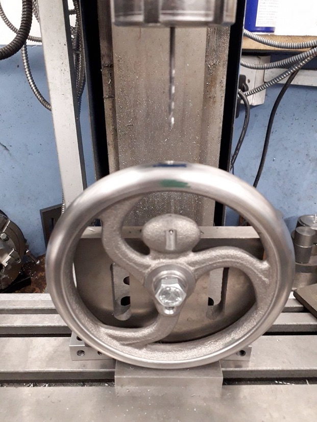
This mark made it easier to line things up when it came to drill the pin hole which is also counter bored and threaded so the threaded pin can be turned to alter the governor spring pressure.
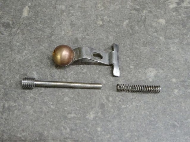
The governor weight is made by modifying a 3/8" diameter bronze ball by adding a hole and turning a small shoulder.
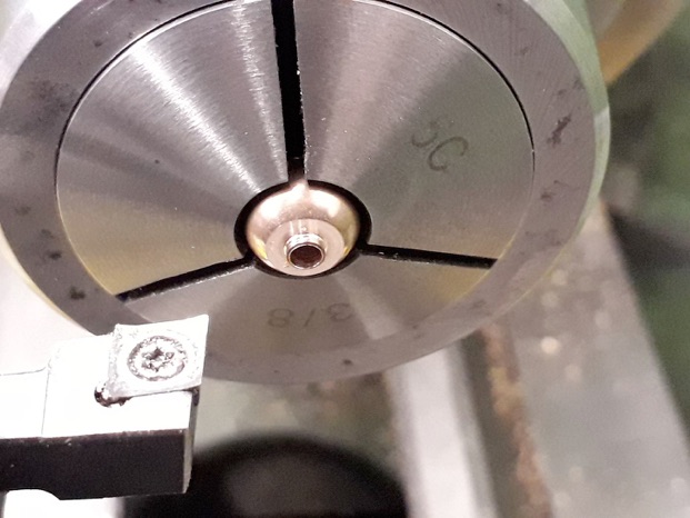
The shoulder is used to locate the ball in the governor bracket while it is soldered in place. In use when running as in hit and miss mode the ball and bracket are thrown out by the force of the rotating flywheel which causes it to move away from the isolated ignition contact so the engine will miss, as things slow back down the bracket will again come into contact with the isolated point and it will hit (fire). governed speed can be adjusted by screwing the long pin in and out which alters the spring tension. To run as a throttler the nut retaining the bracket is simply tightened so it can't move outwards.
The main bed casting looks quite a challenge at first but each operation is listed out in the build instructions and was actually not too hard to do.
First item is to hold in the 4-jaw by the chucking spigot and turn the small pip on the end flat and drill a centre hole. I added some balance weights in the form of a couple of V-blocks and a 15-30-60 block taped and wired on which enabled me to run at about 400rpm before the lathe wanted to start dancing down the workshop. Once the tailstock centre is brought up for additional support the feet can be skimmed flat.
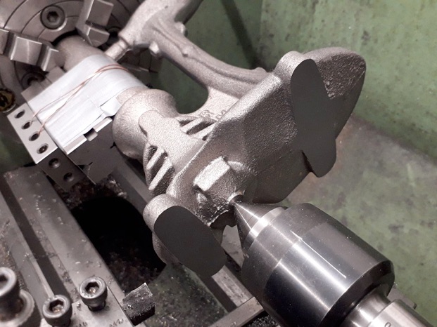
The next suggested thing is to bore the cylinder but I could sense a little bit of movement when facing the pip so did not want to do the bore like this, I think is was due to the chucking spigot being slightly larger at the far end so it could not be gripped really firmly. So I flipped the casting around and clamped it to the faceplate so that I could true up the end of the chucking spigot to give me something even to hold.
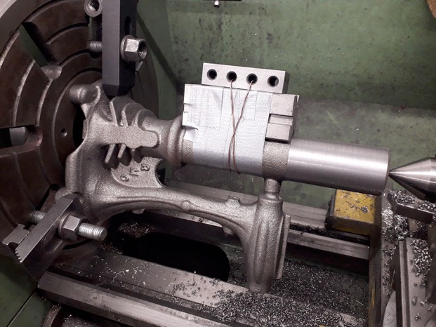
With the bore and cylinder head mating face now machined I brought up the tailstock again and took the slightest skim off the feet to make sure they were true to the completed bore as that would be my ref surface for what followed.









Modelengineeringwebsite.com
the only free and the only weekly magazine for model engineers.
Editor: David Carpenter