BUILDING AN RMC TYPE ‘B’ ENGINE
Part one by Jason Ballamy



BUILDING AN RMC TYPE ‘B’ ENGINE
Part one by Jason Ballamy


I have liked the look of the engines from RMC designed by Nick Rowland for a long time but they went through a period of being hard to get. I managed to pick up a Type-A from a collector who was reducing his stash, then I saw a link to an ebay listing where Nick was selling a small batch of the Type-B castings. Unfortunately, they were all gone but I decided to e-mail him and luckily some more were available so I snapped one up as they are on my small list of casting sets that I would like to make. http://rowland24.20megsfree.com/
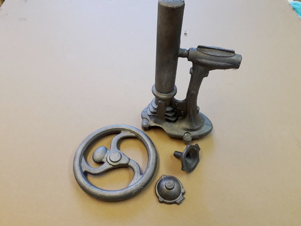
A couple of weeks later the box arrived and as well as the castings and individual numbered name plate it contained one of the most comprehensive drawing/construction packages (example above) you are likely to get together with a CD with several hundred images ranging from some of the original hand drawn sketches, through CAD models to patterns and mould making then machining and finally finished engines. The quite reasonably priced set of castings is shown below - note that very generous chucking spigot to hold the casting for machining.
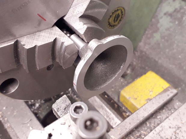
I started with the half that goes towards the engine first holding by the edge of the flange to true up the chucking spigot, in fact it ran amazingly true maybe a thou or two run out but still needed skimming to remove the draft angle. I then had a parallel surface to hold in the 3-jaw chuck to skim the flange which even though it's not much more than 1/8" thick machined easily - no chilled thin sections here.
The casting was then turned around and held by the flange again, I had added the Sharpie pen marks when doing the spigot so it could be replaced in the same position. The spigot was cut off and a hole drilled and bored to a firm fit on some 1/2" steel rod.
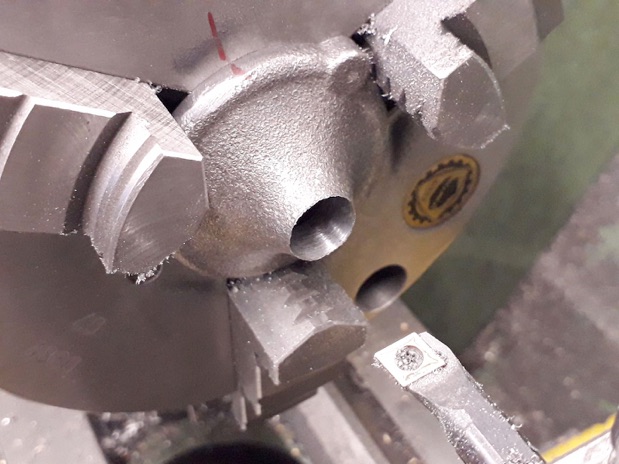
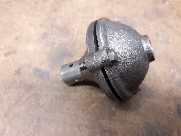
The other half was then skimmed across the flange before reducing the thickness to leave the three bosses full depth which act to space the two halves apart unlike a lot of silencers that have simple turned spacers. I cut until the edge was just breaking through as any more would have risked cutting into the chuck jaws, what little remained was easily files off.

The small stub pipe is simply a piece of 1/2" steel drilled out and then cross drilled for some additional holes, I just used a square ER collet block to index the 4 holes with the back of the nut against the vice jaws to locate the block in the X-axis.

All that was left was to drill clearance holes in one half and tap the other. I opted to use BA fixings on this engine rather than UN, so in this case 4BA rather than #6-32; the hex head fixings here were temporary and I turned up some fillister head screws for the finished engine. The pipe is retained with high temp Loctite 648.
Taking a break from the castings I thought I would do the conrod next, this was roughed out from a piece of 5/8" steel. To produce the shapely big end I drew it out in Alibre and used that to produce a series of co-ordinates at 0.020" spacing which were cut with an insert parting tool.
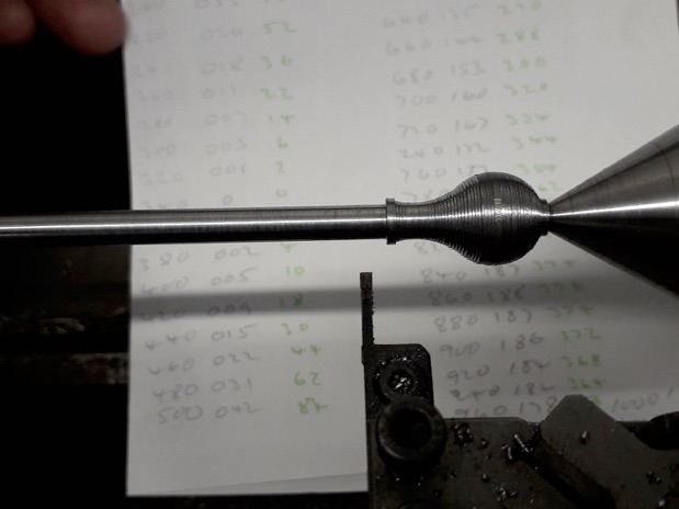

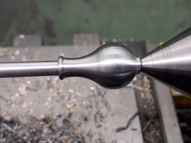
The stepped cut was then blended with files until a pleasing shape was produced.
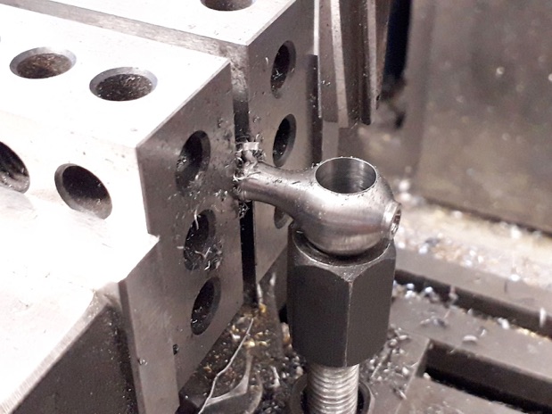
As the distance between big and little ends was less than the width of my vice jaws I used a couple of 15-30-60 blocks as packing to hold the rod for drilling and reaming the ends, I also supported the big end with a make shift jack from some clamping nuts and a stud to make sure it did not deflect.
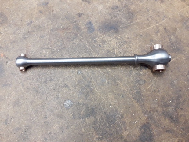
A couple of bronze bearings were turned up and fixed with 648 Loctite and the drilling for the oiler in the big end carried through the bearing.
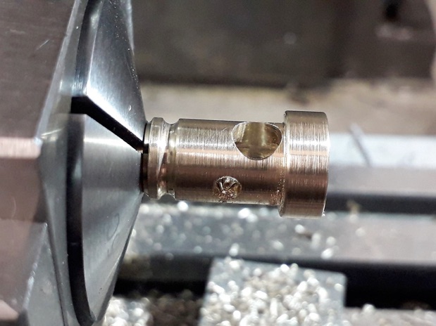
The carb is a fairly simple turning job with a few decorative beads that was then transferred to a 5C collet block to drill the cross hole for the choke and one half way in at 90deg for the fuel line nipple. I must stop taking such close up shots as it makes the surface look rough!
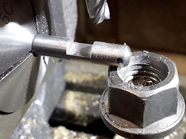
The choke is just a spindle with a hole for the control lever at the end and then milled away either side to form a butterfly; not much metal left so a jack was used again.
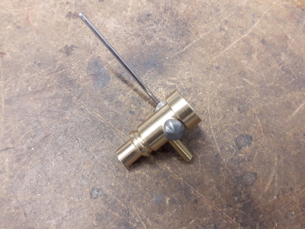
The completed carb, which looks a lot better from this distance, is just a press fit into the hole in the cylinder side.







Modelengineeringwebsite.com
the only free and the only weekly magazine for model engineers.
Editor: David Carpenter