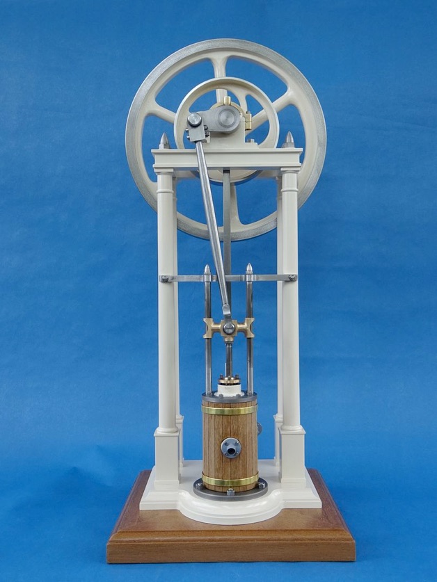
The entablature supplied with the engine is really the ‘wrong way up’ as classic architecture would have the bottom smaller than the top so it flairs out much like the capitals at the top of a column. So a new one was designed to be the right way up and also have a recessed middle band and raised bosses for the bearing supports and column nuts.
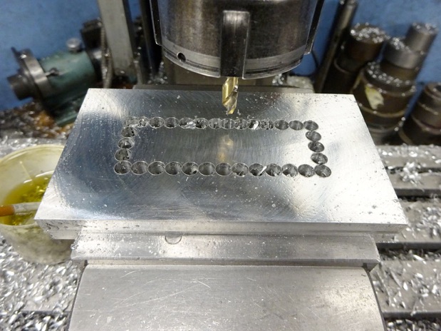
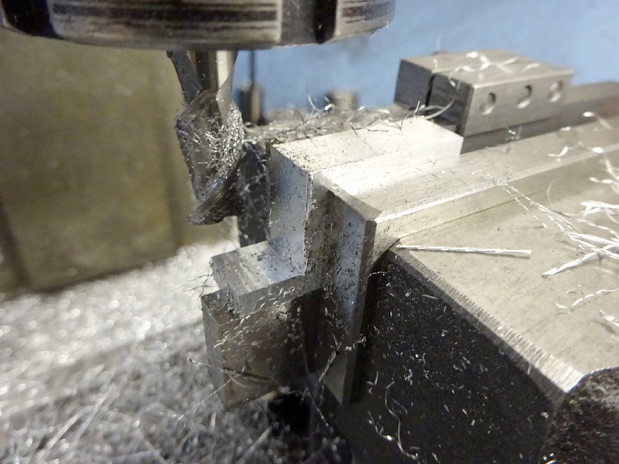
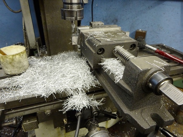
I started by milling down some 5/8" flat bar to 15mm thick with an 80mm insert face mill and then used a 6mm split point stub drill to stitch drill out the waste, These drills don't really need spotting first and being short don't wander into the previous hole. Keep the bit of metal removed from the middle as it will get used later.
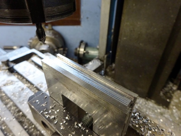
After milling out the rectangle the four sides where milled to profile, for the mid section I used a 6mm cutter with a 1mm corner radius which leaves an internal fillet for that cast look.
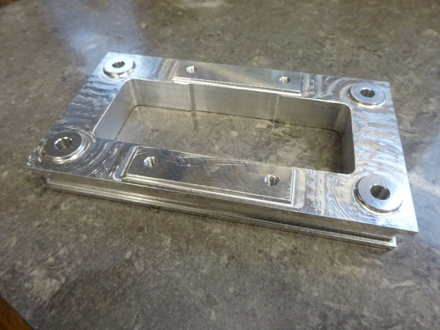
After that the various holes were drilled and the bosses machined with the same corner radius cutter, I used the CNC but if you were doing similar on a manual machine then I would mill the two rectangular bosses but counterbore for the round ones and Loctite in four turned ‘washers’ unless you want to set up for each one on a rotary table. You can also see on the far side of the cut out that there is a deeper section which gives additional clearance to the eccentric allowing it to sit closer to the valve chest helping to do away with the cranked valve rod of the original design.
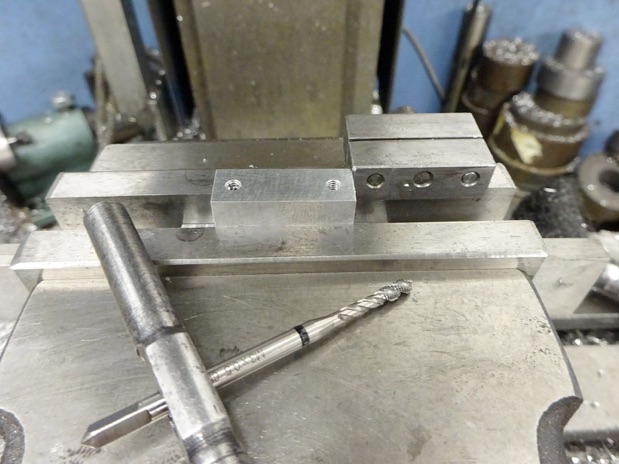
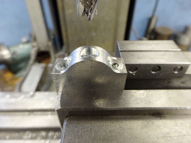
The bearing supports start out as rectangles of aluminium from the same piece that the base was cut from, Milled at each side to leave the feet and then drilled and tapped for the bearing caps.
A two flute carbide cutter specifically for aluminium makes quick work of this taking full depth passes of 1.5mm wide per pass.
A simple vice stop allows the two parts to be swapped over in the vice without the need to keep locating their position and a spiral flute tap removes the swarf from the blind tapped holes.
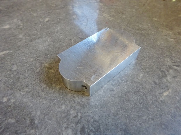
To make it easier to hold the bearing caps while they were machined I cut them on each end of a larger piece of material before cutting them off and cleaning up the cut with a quick skim of a face mill.
Before cutting off I spot faced for the fixings and also milled a shallow counterbore which will have a short length of rod Loctited in, that has been threaded M4x 0.5 metric fine for an oil cup.
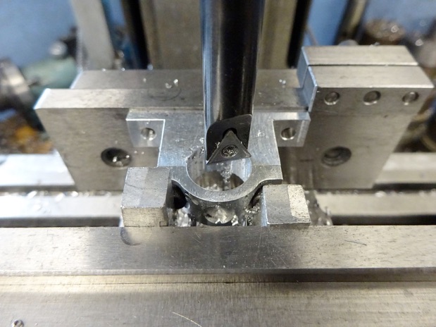
I tend to use cap head screws during construction as they are quick and easy to screw in and undo multiple time s with a suitable ball ended driver. Here you can see them being used to hold the cap to the support while the bearing hole is bored. I have packing on each screw head so that the pressure is not on the crown of the cap which may distort it.
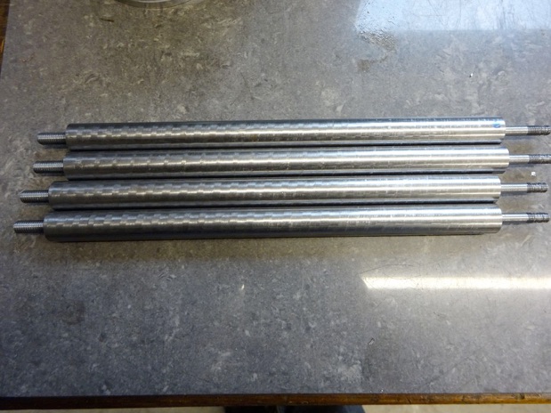
The columns on the engine are quite a noticeable feature, the book just shows them parallel turned to 1/2" diameter from 5/8" stock leaving a small flange at each end and a not "embellish as desired" which I decided to take them up on.
I started out with some 14mm rod, this was ordered as EN1A but was really nasty to machine and also had quite a pronounced spiral finish on the outside. If you look closely at the threads on the right they were tearing and I was not hopeful of getting a good finish on the long slender taper.
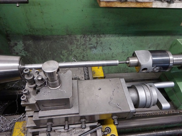
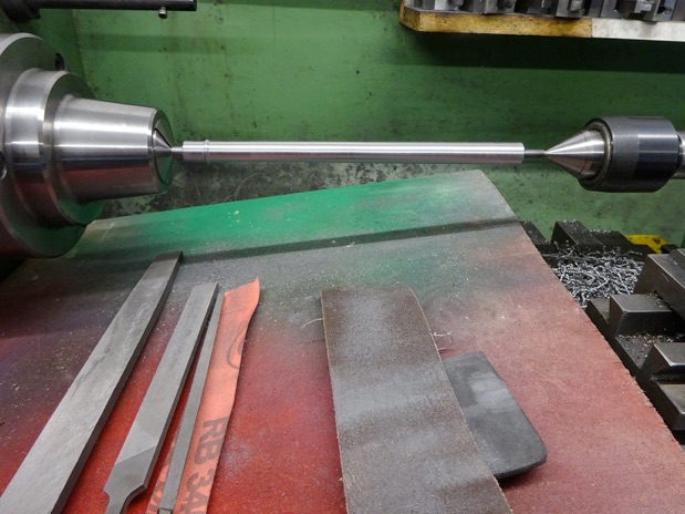
After reducing the top 10mm length to 11mm diameter I then changed setup gripping this short length in the 5C chuck and supporting the other end with a small rotating centre held in my boring head which was offset to allow the taper to be cut. Initial cuts were not good but after trying a few different inserts I settled on a CCGT insert with 0.8mm tip radius which seemed to give a reasonable finish.
Then driving by holding the top spigot I just hand filed the rectangular ring that I had left into a half round profile and also gave the columns a quick going over with Emery cloth to clean up the finish good enough for painting.
Part three here Part five here