CLICK ON DRAWINGS TO DOWNLOAD - FOR PERSONAL USE ONLY.
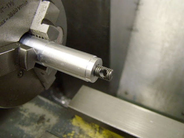
The needle valve parts were next. The needles are made from 16swg piano wire and ground by rotating it on the side of the off hand grinder before running it in the lathe and supporting it at the tip by a piece of hardwood. The tip can then be trued and polished using a worn needle file conventional or diamond. This method produces quite concentric and efficient needles.
This shows one with the lathe running - very little run out
The threaded portion is made from a 7BA screw, held gingerly in a collet and drilled thru then 'reamed' using a piece of the piano wire ground at an acute angle as a reamer. This produces a good 'Loctite' fit on the wire. Constant withdrawal to clear the swarf is necessary as it soon builds up and will jam on the taper.
The pistons were turned from some 1" cast iron bar taken down to 20.0mm diameter, long enough to make the four pistons and contra-pistons. The ODs were turned to 18.5mm and the inside drilled and bored to depth. The inside diameter of the skirt was then relieved to 16.5 mm to fit on the turning fixture and the whole parted off before transferring to the mill to have the wrist pin hole drilled and reamed.
At this stage the internal profile could be milled, after first setting the wrist pin square to the table. This was achieved by holding a slip block against a dowel in the wrist pin hole and squaring up to it by using the rotary table to align it.
The major slot was milled by plunge milling in 1mm steps - slip and dowel removed first.
To lighten it as much as possible the corners of the bosses were relieved .....
Before popping back in soft jaws to turn a relief at the top.
Once this stage was reached they could be mounted on the fixture.....
..... for finishing the ODs and turning to length
The contra pistons were all bored to fit an expanding mandrel used in reverse i.e. the expanding screw removed and the spring of the jaws used to provide the gripping power. This is sufficient to resist turning forces for turning the OD, facing and the turning of the cone recess. Once finished to fit a liner the wall thickness will be reduced.
And all done ready for lapping.
Here are the bead blasted parts
And all the parts ready for assembly.
See part one here part two part three part four part five part six part seven part eight
part nine part 10 part 11 part 12 part 13 part 14 part 15 part 16