DELAGE GRAND PRIX ENGINE PROJECT
Part five by Mike Sayers

DELAGE GRAND PRIX ENGINE PROJECT
Part five by Mike Sayers
This is the very first drawing of the Delage cylinder block side elevation, and a section through the first cylinder. It was dimensioned, but this drawing was all there was to work with initially.
This cylinder block assembly sits on the crankcase, and it was very easy to decide to make it in four parts:
o The base plate
o The cylinder liners.
o The water jacket which encloses the cylinders.
o The top component which contains the sixteen valve gear cam mounts, the spark plugs etc. This is a separate part that will drop on the top of and locate on the cylinder liners. This is very similar to the arrangement on the 1:3 Scale 3 litre Bentley engine.
The only problem is in the top component. As can be seen on the section, there are only two planes that are parallel. The other faces are at either at 30° or 40°. This makes it very difficult to work out a datum.
The intention was to have only one datum on each drawing, and all the dimensions would be taken from that datum. A datum, however, was chosen which will be described later.

There is a parallel ‘fence’ bolted to the machine bed with a stop at the end. The component can then be put up against the parallel, and against the stop.
It was decided to move the longitudinal datum to the centre of the first cylinder.
The component had to be precisely centred on the bed, otherwise once the cutter got to the other end, it would have run out of movement.
The previous photo shows the job finished with the packers and parallels removed. The “threepenny bit” items are Mitee-Bite clamping devices. They fit in the T-slots, and work around an eccentric headed cap screw.

Using a 4mm ball-end mill, it’s just a question of setting the datum, and then moving it either side and rotating the component back and forth in the dividing head, so that the requisite curve is machined. The process is repeated at each location until the other end is reached.
Using a ball-ended mill results in a bit of a ‘tramline’ surface, but it is easy to dress that off at the end, with a needle file.
Machining the cylinder liners


All fit well.
Note the ridge near the base of each liner that will support the water jacket.
Machining the water Jacket
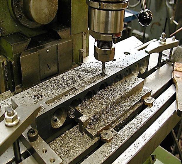
The water jacket is another block of cast iron that needs to be machined, using the same clamping setup as the base plate. There is a lot of machining here, with the Mitee-Bites used to clamp the block against the parallel fence.
Here the access openings in the side of the water jacket are being machined. These will eventually be closed by screwed on water plates.


Part one here. Part two here. Part three here. Part four here.


Modelengineeringwebsite.com
the only free and the only weekly magazine for model engineers.
Editor: David Carpenter