JAMES COOMBES ENGINE REVISITED
Part three by Jason Ballamy

JAMES COOMBES ENGINE REVISITED
Part three by Jason Ballamy

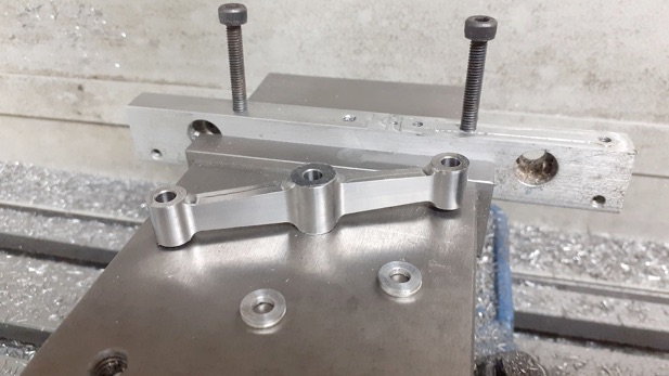
I did most of the crank on the CNC - drilling, reaming and shaping. In this photo I have just completed the milling of a web between the two bosses which was done with a 4MM dia cutter with 1mm corner radius to leave a fillet for that cast look.

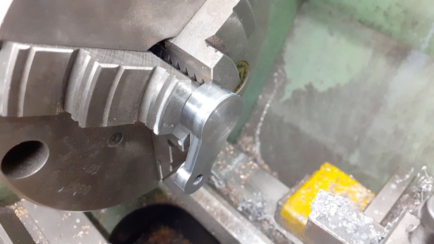
After machining it was Loctited onto a 10mm spigot that had been turned on the end of the 12mm PGMS crankshaft and once set was faced off ensuring the face was at right angles to the axis of rotation.

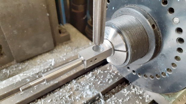
Stuarts show a soldered construction for the tuning fork shaped conrod but I decided on a bolt together one similar to that used on the Waller table engine. I roughed out the stock on the manual mill and then thinned the ends and reamed the holes on that machine, too.


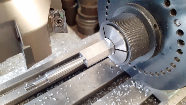
The short leg of the conrod that has the big end was turned from some 16mm dia stock, first doing the 4mm dia section before pulling out some more material for the half fish bellied rod.


.Part one here Part two Part three Part four