...continued
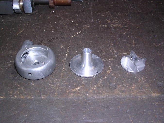
Onto the pump cover/inlet which is a fun piece of turning. I drilled and tapped for four 10BA screws to secure it.
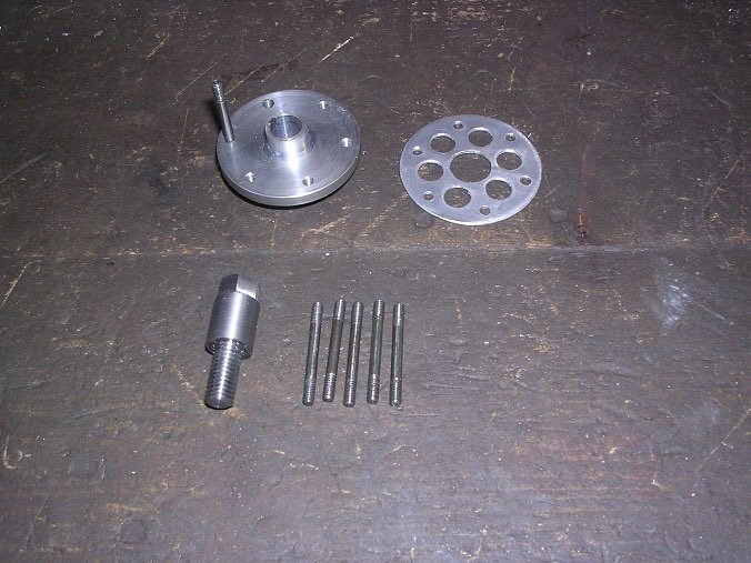
Then the propellor flange. I felt that it should be secured using studs and a cover plate and so laid them out.
The effect is quite pleasing. I also took the opportunity to try the timing gears for mesh. They are OK too!
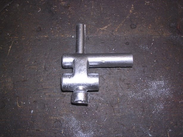
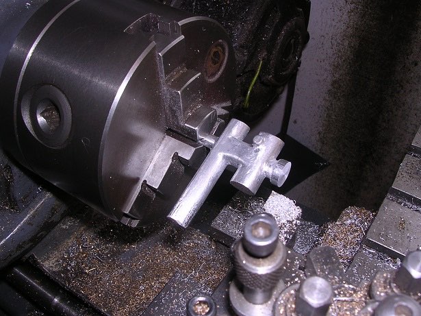
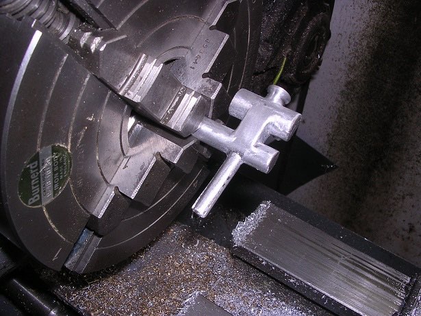
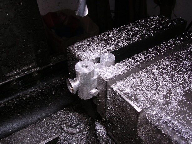
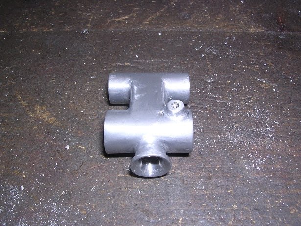
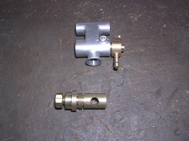
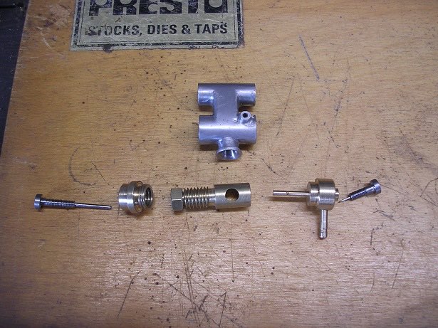
The carburettor starts as a small casting with a couple of chucking pieces. They help no end but it is still a pig to hold. There is not much metal around to spare either.
Holding it for the second hole was a challenge. I think I cut the chucking piece off too early but I got away with it in the end.
The throttle is a barrel type with two outside threads and an internal one with a cross-hole to boot.
I lapped it into the housing using metal polish.
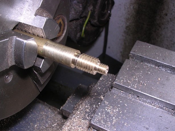
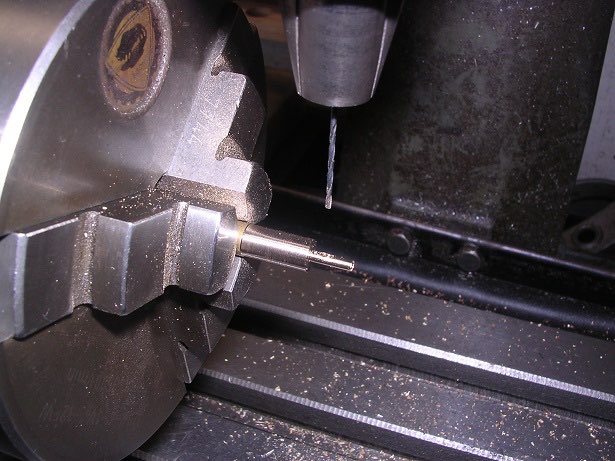
The fuel inlet tube was very tricky and I made quite a lot of scrap. It is 2mm OD, 1.5mm bore with a 1mm cross-hole and 0.5mm orifice. The main problem was in getting the machining sequence right. I started by putting the cross-hole in first while the brass was at maximum diameter and stiffest. This turned OK afterwards but when drilling the bore, the bit wandered out of the side and the tube bent. I eventually settled on drilling the bore first, turning the OD to diameter in steps so that I could put the cross hole in next to the largest diameter and then returned it to the lathe for final turning. On parting off, I reversed it and drilled the 0.5mm orifice from the other end, holding the chuck in my fingertips so that I didn't break the bit. I succeeded but it was a bit of a painful exercise.
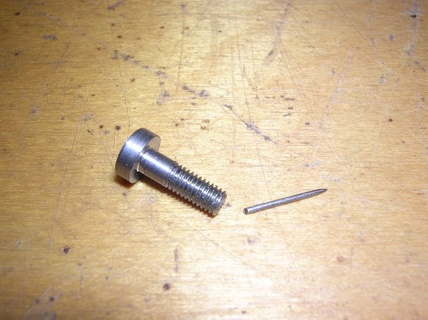
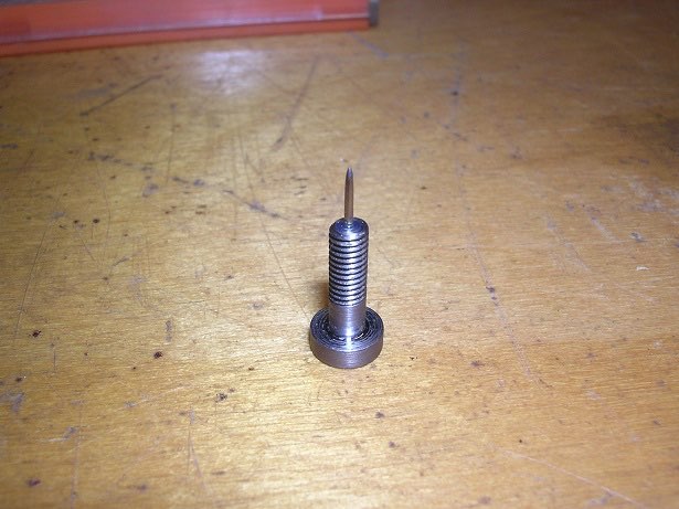
Then turned up the needle valve for the jet and the mixture control. The 'needle' is really a pin stuck in a hole with Loctite.
A kit of parts ready for assembly.
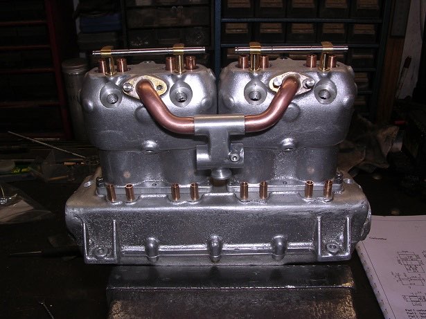
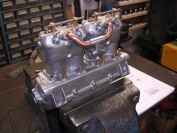
I fitted the carburettor body to the inlet manifold tubes using Loctite. The bolt holes will need easing slightly but it is beginning to look nice.
Part 19 here