... Continued
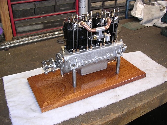
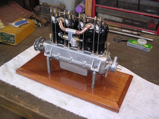
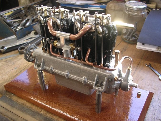
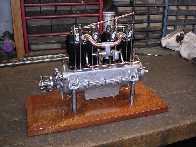
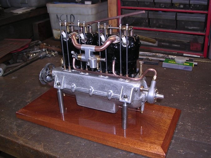
I have been getting concerned that I might knock the engine over and do some damage so I have made up a display stand to keep it safe. Being a miserly type, when I last broke up some old furniture, I kept the drawer fronts which were mahogany. I found one in the garage and despite being well beaten up, it cleaned up nicely and was just the right size. You can't have too much 'stuff' in your shed!
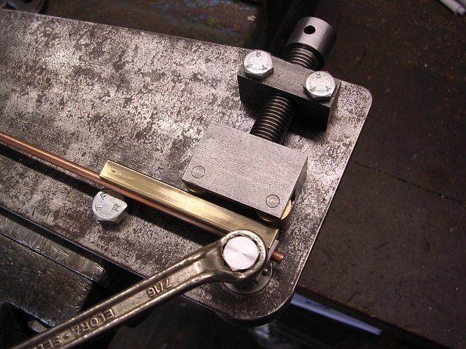
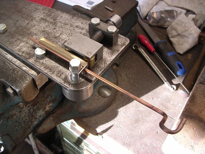
For the water pipes, starting with the pipe bender, I didn't need to make a bullet support to stop it crushing this time.
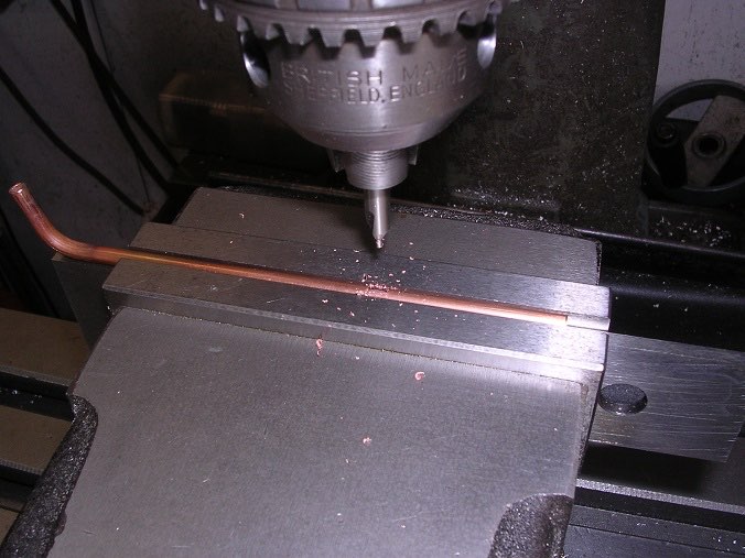
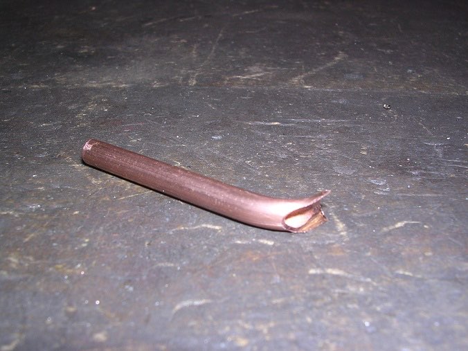
Then a slot for the centre pipe.
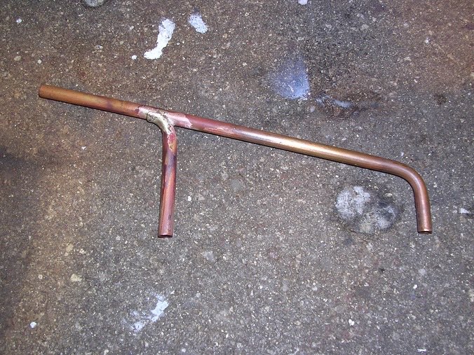
I bent the centre pipe and then filed half away so that it sat on the main pipe for soldering.
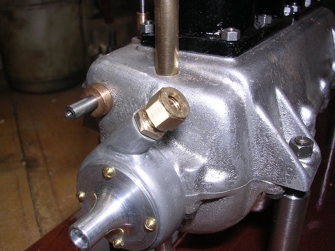
After cleaning and pickling the return pipe assembly, I turned up a union for the pump. None of this is shown on the drawings so it was a case of making it up as I went.
Then onto the inlet pipe. This is a fiendish bit of bending as I had to rotate the water pump to miss the distributor so the outlet points the wrong way.
Stb pipe in place ready for soldering.
And that is it, mechanically complete.
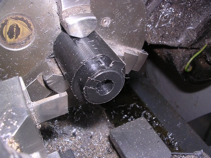
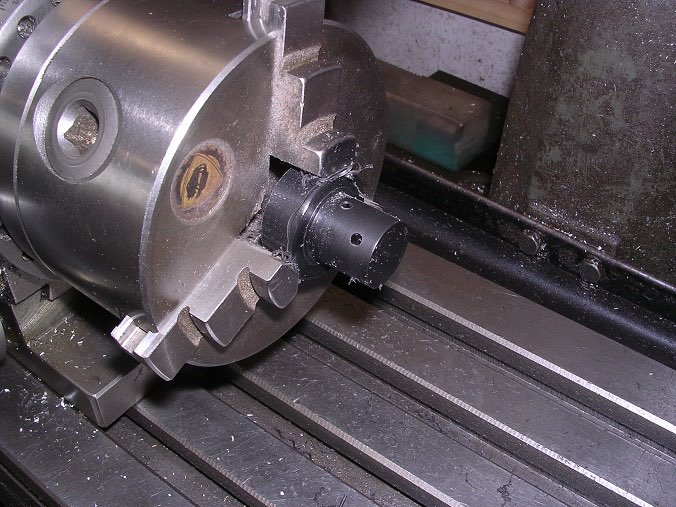
The ignition system drawings are not very helpful and specify 'insulation' as the material so I have taken some advice and have acquired some 'Delrin'. To practice with this material, I made the centre body of the distributor which is a simple tube and I must say that it turned beautifully. I then went onto the end plate which has a boss and pinch bolt to secure the unit to the camshaft bearing.
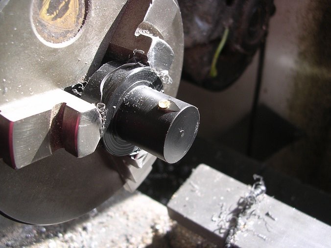
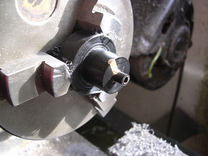
Rotor arm/contact breaker next. The rotor arm is a piece of brass rod pushed into the side and then partially machined away. I pressed the first one in with superglue but, not surprisingly, it hydraulic locked and I couldn't push it home with the result that I couldn't make contact at the centre. I did a second one after drilling the centre hole and that was fine.
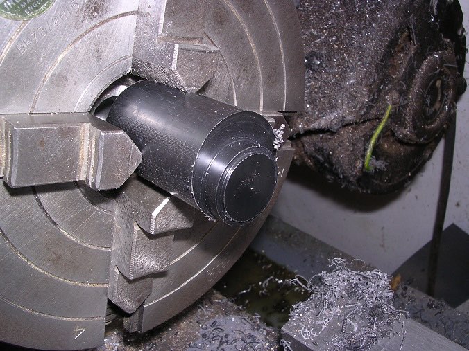
Then the distributor cover. This was a fiendish bit of turning but went OK in the end.