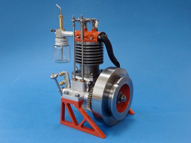


The crankshaft started out as a length of EN8 steel that was faced to length and centre drilled for the throw and shaft centres before milling out most of the waste around the pin, which is much faster and easier than turning it away. I left it for a week to settle after this but it did nor show any signs of having moved.

Then the pin and inner webs were turned, I used a boring bar for the left hand web and an HSS knife tool for the right, the pin was completed with a modified parting tool that has had the middle of the cutting edge ground away with a Dremel which stops any chatter as the tool is worked from side to side as a fine cut is put on.

I then rough turned the ends down using a holder that takes the ‘other two’ corners of a CCMT insert while holding the web in the chuck.

Final finishing was done between centers using a DCMT insert which again helps reduce chatter and will also take off a fine cut.

I also turned and rough bored the flywheel at this stage, but more of that later.
Last jobs for the lathe were to screwcut a thread on the end and then cut the taper for the flywheel, doing it at the chuck end makes it easy to bore the flywheel at the same top slide setting.

Finally back to the mill to shape the webs to give some counterbalance.

Before doing the taper on the crankshaft, the flywheel was machined. First job was to recess the sides of a slice of 80mm EN1A steel. By setting over the top slide two degrees some draft angle could be included on the outer edge while turning conventionally.

Then by running in reverse and working on the rear side of the hub that could have the same taper, and by noting the top slide/hand wheel setting, it was easy to machine to the correct depth. A tool with a rounded end was used to again give the look of an internal fillet as found on castings.

I could now set the top slide to the correct angle for the crankshaft taper, and then use that to gauge the depth of the flywheel's tapered bore, all without altering the angle so both tapers matched. Fine cuts were taken until the shaft entered the flywheel and left 0.5mm clearance between the assembled bearing and timing gear.

Without altering the top slide angle I also machined a tapered arbor and pushed the flywheel onto that using a block and the tailstock centre to make sure it stayed in place which allowed me to skim the OD to a true finish relative to the bore, and cut the recess for the starting cord.

The arbor did not go to waste, a slot was cut so that it could be used as a bush when broaching the flywheel.

Part one here Part two Part three Part four Part five Part six Part seven


Modelengineeringwebsite.com
the only free and the only weekly magazine for model engineers.
Editor: David Carpenter


