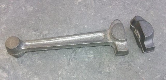
The con rod is supplied as an iron casting with another casting for the bearing cap, one unusual feature is that the cap is pivoted much like a hinge on one side with a single bolt to the other, as there is only access into the crankcase from one side.
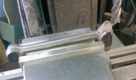
Making use of a step in the casting halves and the machining allowance at the other end, the main rod was taken to width and a light skim taken along its length so I could hold it by the I-section if needed.
Luckily the ends just fitted in the vice so held by them the central part of the hinge was milled to width, then the part reversed to take the face back to the joint line.
The bearing cap was machined in much the same way adjusting the hinge gap until it fitted snugly onto the con rod.
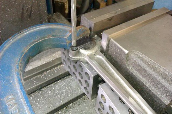
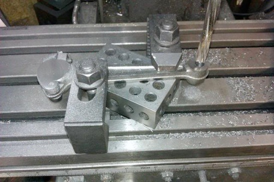
Then using a G-clamp to hold the two halves together, the vice to stop it all moving about and some 1-2-3 blocks for support, the hinge pivot hole was drilled and reamed.
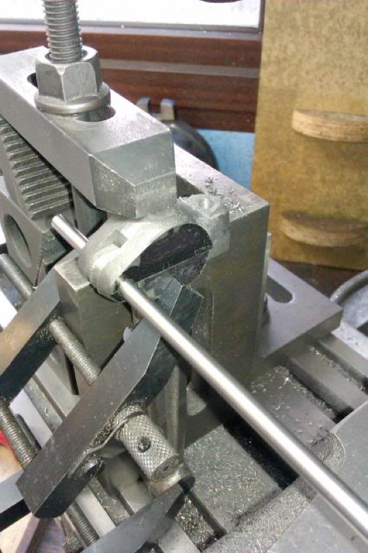
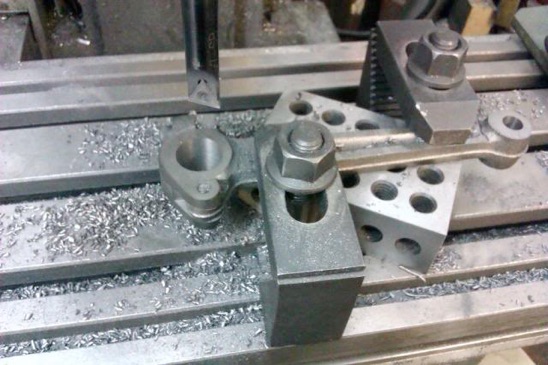
With a length of silver steel (drill rod) as a temporary hinge pin the hole for the bolt was then drilled with the job held to an angle plate with assorted clamps.
Now I could make use of the skimmed side of the I-beam to support the rod while the little end was drilled and reamed and at the same setting a boring head was used to open up the big end to 3/4" ready to take a bearing.
Finally, a bit of hand filing to clean things up and a quick whizz around in the rotary table to make the big end look a bit more presentable.
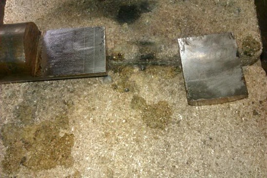
The big end bearing was made in much the same way as the others, tin two bits of bronze, sweat together and then machine.
The small end bearing is just a simple turning job and then pressed into the casting and that’s another part ticked off the list.
Part 1 part 2 part 3 Part 4 Part 5 Part 6 Part 7 Part 8 Part 9 Part 10 Part 11

