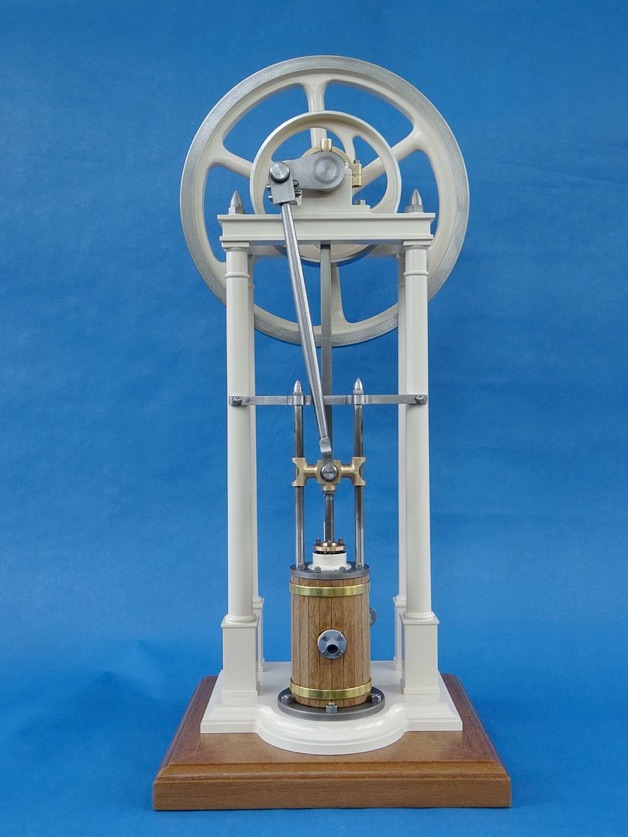
A slice of cast iron was held in the soft jaws and turned to the diameter of the cylinder top cover; faced and cut the spigot, then spotted and drilled 4.8mm with a stub drill. Finally, took the hole out to the required 5mm diameter with a machine reamer.
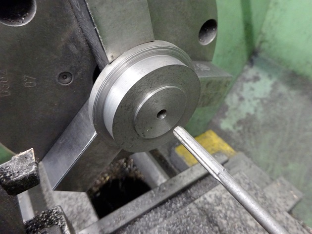
Holding the other way round, the boss for the gland was turned leaving a flat area for the nuts. I used a brazed carbide tool with a rounded nose to get the larger fillet at the base of the boss.
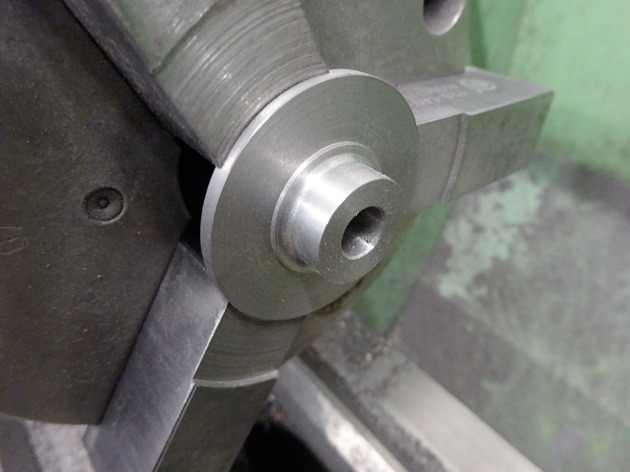
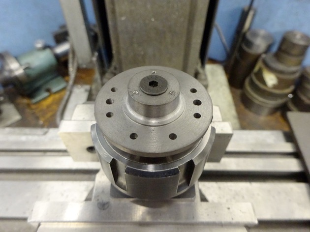
With the cover screwed to an arbor which in turn was held in an ER32 block the outer edge was kept clear so the edge finder could be used to locate the cover's centre then set about drilling some holes. Eight @ 2.5mm for the studs, two @ 3mm which were CSK on the underside for the cross head guide rods and three @ tapped M1.6 for the gland studs.
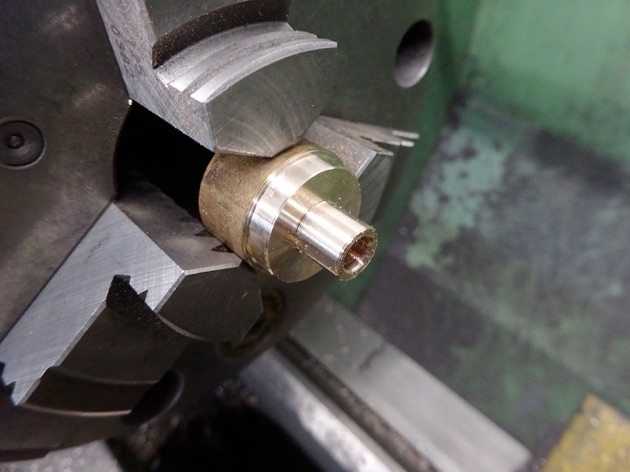
The gland was quite straight forward turning to fit the cover and reaming for the piston rod.
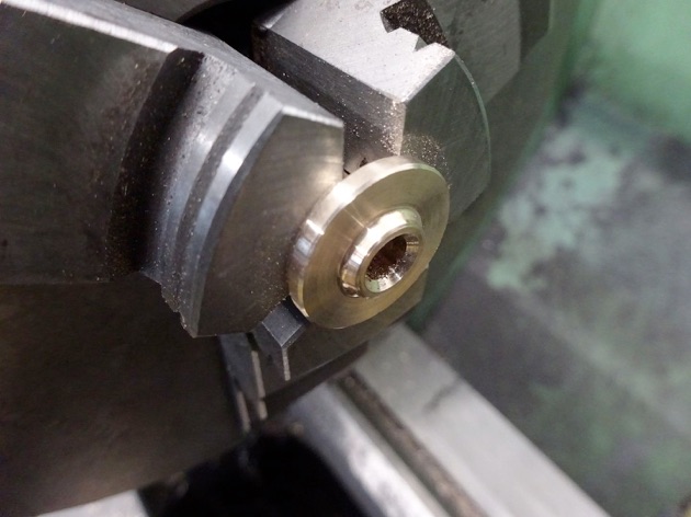
Then held the other way round to face off, add a decorative spigot and CSK the hole to encourage any oil back into the cylinder rather than running over the engine.
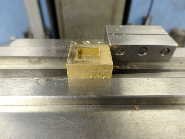
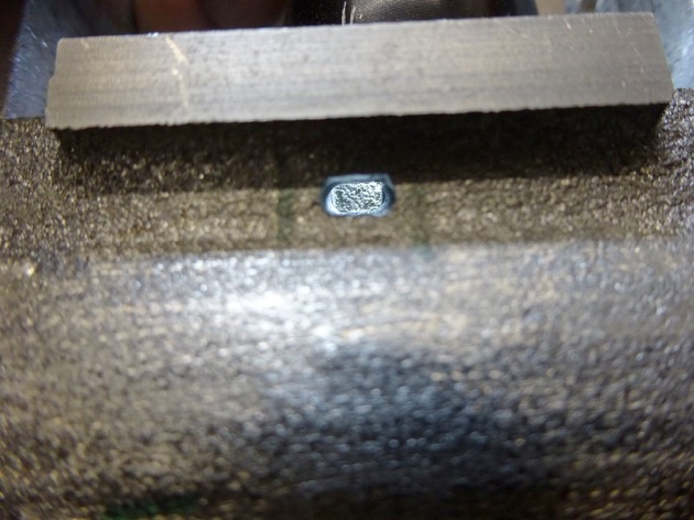
Another small part tackled at this stage was the valve, just a piece of bronze milled to the overall size and then the recess milled into one face with a 2mm dia cutter.
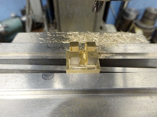
The opposite face had slots cut to clear the valve rod and at 90degrees to that one to take the valve nut which was just a off cut of brass left from the eccentric strap.
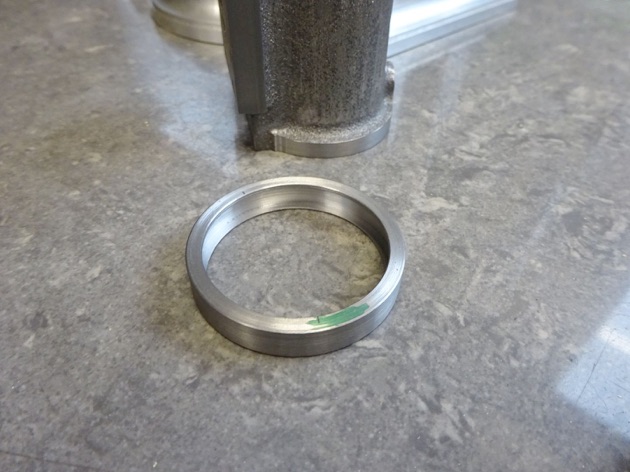
Returning to the cylinder and time to reposition the exhaust connection from the of the valve port face to the opposite side of the cylinder which is a bit less cluttered by columns and the now repositioned inlet. A piece of steel was turned to the same diameter as the cylinder end flanges then bored to the average diameter of the cylinder body. I then used an internal grooving tool to hollow it out to a sort of rectangular U-section.
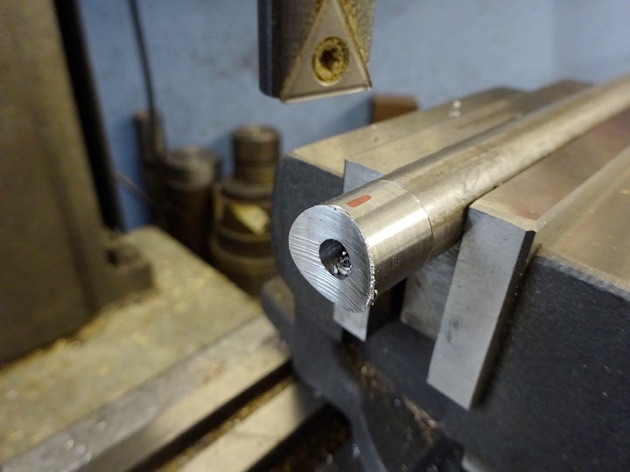
A 14mm diameter was turned onto the end of a bar and the Soba boring head used to cut a radius to match the outside diameter of the cylinder.
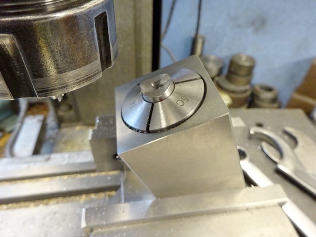
Then holding it in a collet block two grooves were cut that would allow the air/steam to flow from the new passages around the cylinder into a drilled hole in the boss and out to the plumbing.
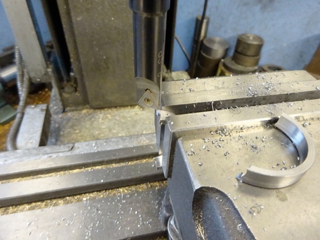
After sawing a couple of pieces off one end was cope cut to suit the 14mm dia exhaust boss and then the other ends fitted by filing until they sat nicely against the back side of the port face.
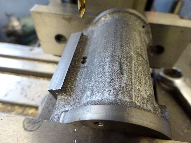
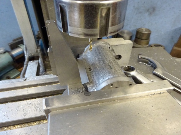
Two holes were then drilled on either side down to meet the central port. I used CAD to work out the angle of the holes and set the cylinder using an angle gauge.
Finally a bit of needle file work had the two holes formed into a slot which was too deep to get all the way with a milling cutter. At the design stage I had made sure that these slots, the new ducts and the slots in the boss were all greater in area than the smallest port the air/steam would have to pass through so as not to restrict flow.
Part 7 here Part 9 here