As I doubt my engine will ever do enough hours for the need to adjust the bearings I did not bother to make them split, I just turned them from bar. The inside was bored to get the fit I wanted on the crankshaft and the waist in the middle to fit the bearing supports before being parted off.
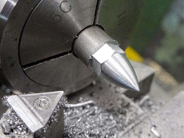
The M5 acorn nuts were made from round bar milled to one size smaller hex (7mm) and then the ball turner was used to shape them, the triangular insert has the advantage of leaving a nice chamfer on the top of the hex. After parting off they were held in a hex collet, though a 3-jaw would do, and drilled and tapped M5. While the ball turner was set up I also made two M3 versions to go on the top of the crosshead guide rods
Here are the bearings and nuts in place.
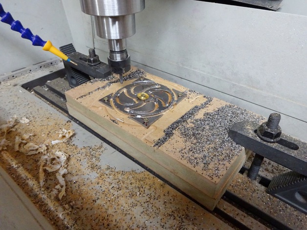
You may also notice in the above photo a slice of ERW tube which is the basis for the more attractive pulley rather than the standard cast Stuart item that they use on all the 2 x 1 engines. The spokes were cut from a piece of 2.5mm steel sheet which was quite easy on the CNC but all the curves are parts of circles so could be done on a rotary table.
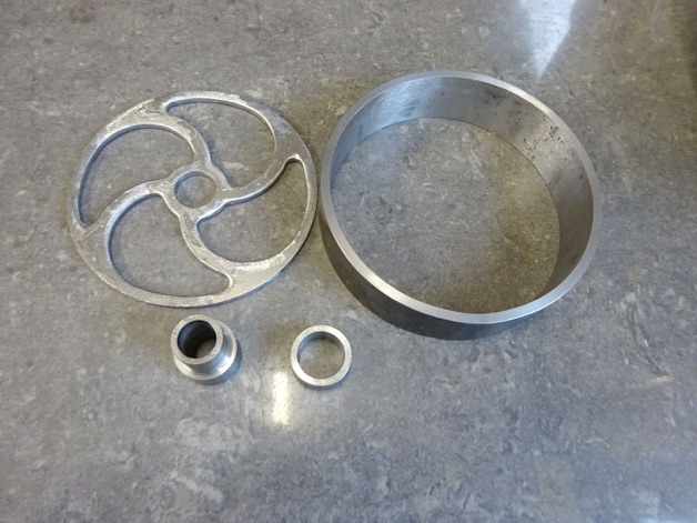
After a bit of ‘softening’ with the Dremel, and turning two bits of steel that will form the hub, all were ready for soldering.
Held in the 3-jaw the outer face was cleaned up followed by the edge of the rim and hub and finally the undersize hole in the hub was bored out to fit the crankshaft.
I then swapped to external jaws so that the other side could be finished.
That's another part that can be crossed off the list.
Part six here Part eight here