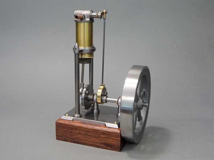
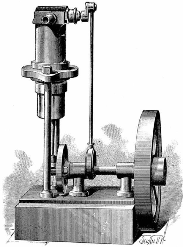
Starting with the 1881 article I decided to alter the published construction methods and add more detail. For example, the text suggests that the plate supporting the cylinder be sandwiched between two threaded rings with the threads being hand chased and the assembly then being soft soldered together. I opted to make the plate and the two rings as one then fix to the cylinder with Loctite.
Strangely, it suggests the cylinder head is a casting with what looked like cored passages. I opted for an inserted sleeve to form the ports for the rocking valve's spindle to rotate in. Rather than brass on brass I opted for a piston machined from steel.
I set about drawing the project up to suit some thick wall brass tube that I had for the cylinder, and that dictated that I use a 19mm bore, making my metric design is about half size.
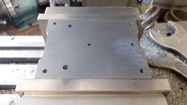
For a bit more detail and ornamentation and not the rather plain flat plate of the original engine’s base, I went to a couple of images of this engine in my "future projects" file and like the edge detail it featured.
So after milling some 5mm plate down to size and drilling the various holes I started by using a 10mm cutter to do the recesses along the edges.
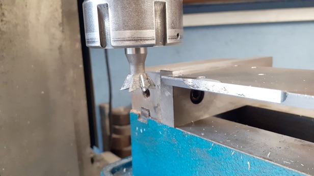
After that the plate was held upside down and a dovetail cutter used to chamfer the edges to a height of 4mm which left a small 1mm vertical edge around what would be the bottom.
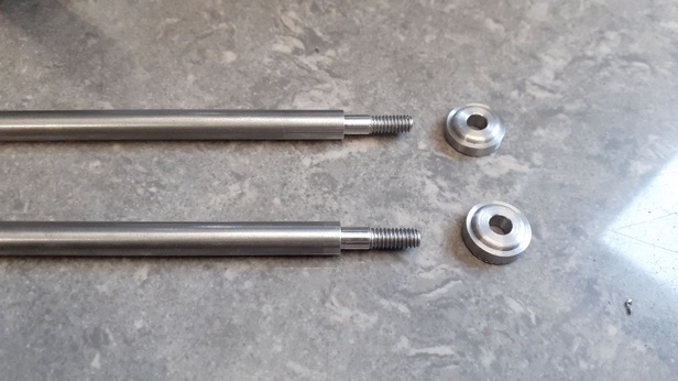
I deliberated for some time on whether to stick with parallel columns or to taper them, in the end straight won so it was just a case of turning spigots on each end that were threaded M4. Two bases were turned with a bit more decoration to the profile and then parted off over length.
The feet were attached to the longer bottom spigots with Loctite and once set were faced back to give the finished length from underside of base to the shoulder at the top of column
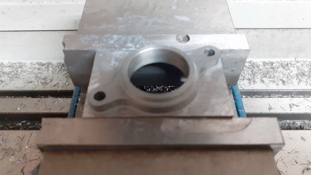
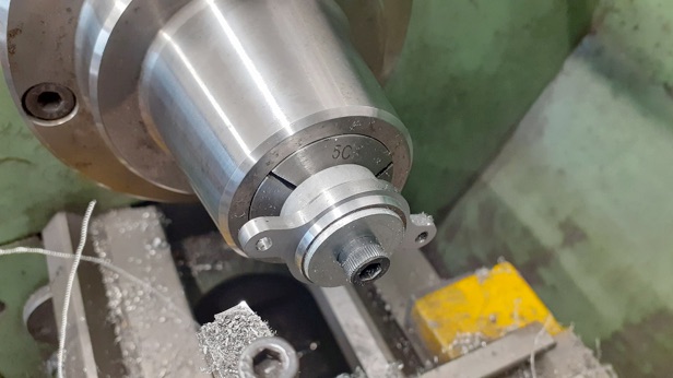
For the cylinder support a piece of 8mm flat bar was held in the 4-jaw and bored to 22mm then the integral upper collar formed by turning 2mm off the face of the bar.
I took the option to profile and drill the two holes on the CNC but it could also be done easily enough with a rotary table. This is a good example of why someone would want a good range of different height parallels, with 8mm stock and a 6.5mm depth of cut having the right parallel so you are only holding the bottom 1mm of the stock ensures you should not cut into the vice jaws.
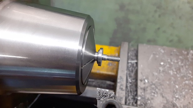
An old arbor was reused to hold the work while the thickness was reduced to 4mm leaving just the lower collar standing proud by 2mm.
PART ONE HERE PART TWO PART THREE PART FOUR