The piece of thick wall brass tube that I had came out at 22.7mm by the time the chrome plating had been skimmed off so I opted to use a M22 x 0.5mm thread for the gland nut that seals the end of the piston (no rings). I opted to make the female thread first and rather than single point cut it I took the opportunity to have ago at thread milling on the CNC. So an odd bar end of 1" brass was held in a 3-jaw chuck, the end milled flat and then the threading size and smaller clearance hole were bored with the CNC followed by thread milling.
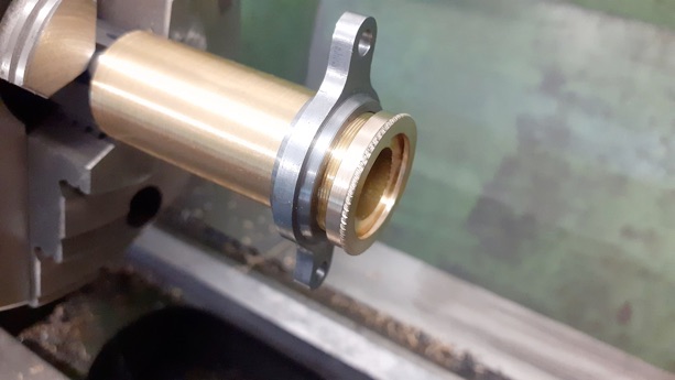
With the internals done I cut a test make thread on the opposite end of the stock and screwed the gland nut onto that to do the remaining turning, the final operation was to use one wheel of a diamond knurl to add a rope type knurl to a half round bead that had previously been turned.
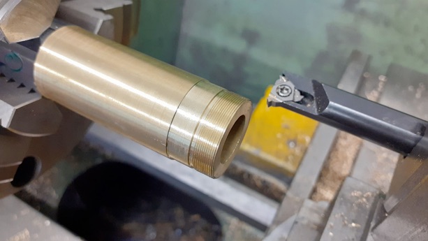
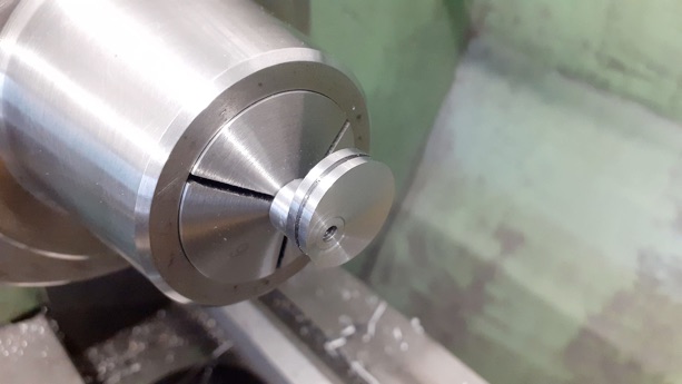
With sufficient length sticking out of the chuck the chrome was turned off the other end of the tube and then a 12mm length reduced to 22mm dia which gave a shallow shoulder to locate against the cylinder support plate. Following that the thread was cut, I find it easier to run the lathe backwards and bring the tool in from the far side, that way I can cut at several hundred rpm and not have to worry about overrunning the length of thread if I don't stop the lathe when required
After checking the fit of the thread using the gland nut as a gauge I bored out the tube to the desired 19mm diameter. It was then sawn off and the top faced back to final length.
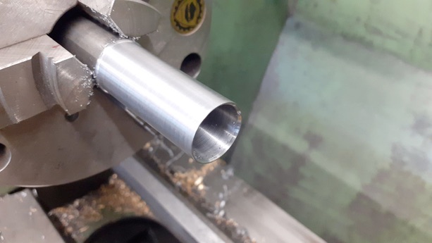
A piece of 20mm leaded steel was turned to fit the cylinder and then bored out to 17mm to leave a 1mm wall thickness, sawn off, faced to length and a 3mm hole put into the top ready to receive the small end yoke.
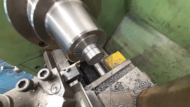
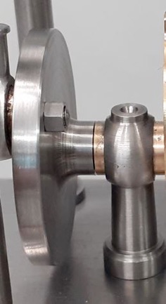
The crank disc was roughed out and then a RCGT 06 button insert used to finish the back edge and give a nice large fillet to the protruding boss and then the hole was spotted, drilled 5.8mm with a stub drill and reamed 6mm before sawing the disc off of the piece of steel bar. It was then Loctited onto a length of 6mm precision ground mild steel and once that had gone off the front face was turned to final thickness thus ensuring the face was perpendicular to the shafts axis.
The bearing supports that can also be seen in the photo above were turned from 12mm leaded steel using a ball turner to form the top and a 1mm radius tool to turn the tapered column so it blended in nicely to the ball. Moving over to the mill 3mm was taken off opposite faces and an 8mm hole drilled and reamed through to take the bearing. Back into the lathe a parting tool was used to form a 3mm dia spigot that could be threaded once cut off for a nut to hold the support to the base.
Bearings were simple turning and reaming from Colphos and Loctited into place after which the oil hole was drilled through.
After turning the OD of the eccentric a 1mm parting insert was used to cut a central groove to retain the strap.
After tapping for a M3 grub screw the eccentric was mounted on a 6mm bar so the sawn face could be turned back to the final 5mm thickness.
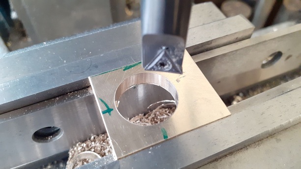
A piece of brass was square dup and then milled to 5mm thickness before boring to size using the eccentric to gauge the fit.
The outside profile was done on the CNC but could quite easily be done on a rotary table or even with filing buttons depending on what you have available.
The eccentric rad was just 2mm dia steel threaded at both ends and the end that screws into the strap had a small spigot turned to locate in the groove of the eccentric.
For the top end of the rod I kept the ball shaped theme going when making the rod eye.
PART ONE HERE PART TWO PART THREE PART FOUR