BUILDING A TIGER TANK

Part 2 by Vince Cutajar

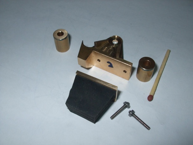
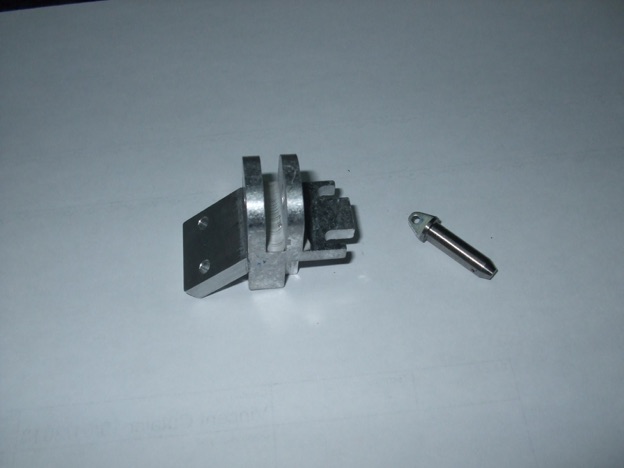
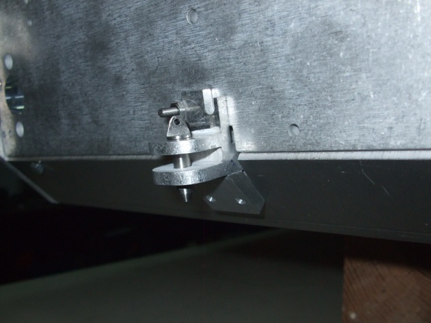
Made a modification on the tow bracket. At first I was going to do it from scratch but then decided to use the kit part and just add the lower part. Initially glued together with JBweld hoping it will stay together until I mark the lower holes with a transfer punch. Also did the tow pin in stainless.
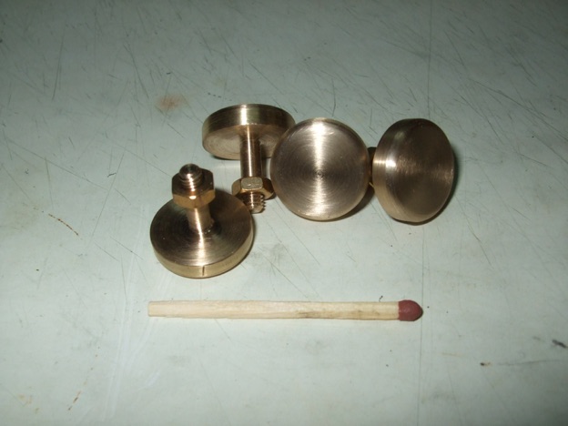
Finished the four shock absorber mounts which should be correct for a late version Tiger. 18mm diameter and 4.5mm thick with a decent rounded edge.
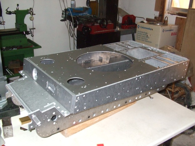
I decided to continue test building the hull to check if it ends up square for the hull deck. During this process I encountered a couple of hiccups and a fitting problem. Literally following the assembly manual and I always thought it was strange that no washers are depicted in the diagrams. Then I found a bag full of washers!  

Another thing I noticed following the manual was that the Upper Front Deck (CE3157 in the parts list and CE2157 in one of the diagrams) was skipped. This wasn't the end of the world as I figured out how to fix it to the hull. It took me more time to figure out that there is a mistake in the reference numbers. I noticed this before with some other parts.

The fitting problem was to do with the Glacis Plate (CE3160 on the parts list and CE2160 on the diagram). It did not fit properly on one side.
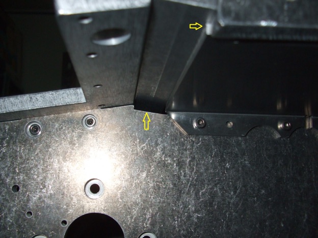
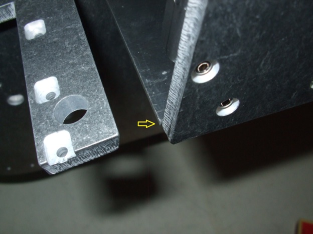
I figured out the problem. The Pannier floor on that side is a little too long.
A little work with a file should solve the problem later on during the proper assembly. I am happy to say that the top of the hull ended up quite square for the top deck. What's the English expression? Quite chuffed?
I finished all the parts for the four bump stops.
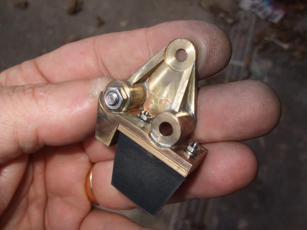
It is true what they say about having a problem and sleeping on it. I can still vividly remember the dreams I had in trying out various methods of soldering the parts together. This morning I cleaned up the parts and used solder cream to soft solder. For heating the part I used a blow lamp with one of those disposable canisters. For the second one I thought I would try some thin electronics solder instead which gave better results.
Not perfect but close enough. Paint is good to hide all the sins. I made the mounting holes 4mm diameter instead of 3mm as a 4mm nut looks better.

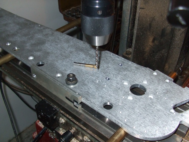
Started "butchering" the floor panel countersinking some of the holes and drilling holes for the rectangular access panel. The setup in the following photo is a bit ‘iffy’.
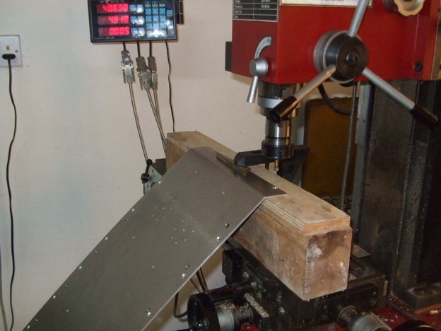
That is the only way I could hold the plate to countersink the holes on the bent part of the plate. Fortunately, it worked.

Next the process of plugging up the unwanted holes using JB Weld especially for the larger holes.

Had a look at the axle assemblies and as the suspension arm mates with two shafts which are threaded and glued I thought that a good clean of the suspension arms was required. So, I cleaned them in an ultrasonic bath to remove all the muck from the female thread.
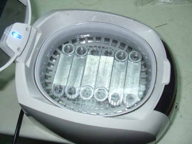
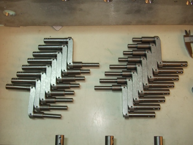
I assembled the axles.
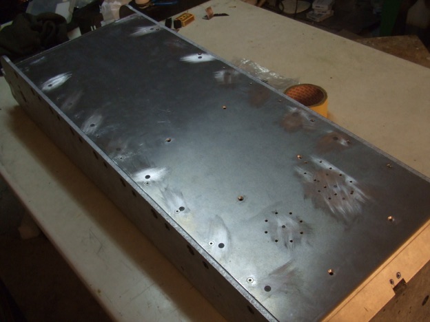
I then sanded flat the JB Weld I had used to plug the unused holes in the floor plate. Trial fit with the countersunk screws was successful.
Disassembled everything for the last time. Drilled holes for bump stops, shock absorber mounts and track deflector assembly. Plugged the unused holes.


Part one here. Part 3 here.

 
https://www.sarikhobbies.com/model-engineer-builder/

Modelengineeringwebsite.com

the only free and the only weekly magazine for model engineers. 

Editor: David Carpenter