BUCYRUS ERIE 50-B
STEAM SHOVEL
Conclusion - by Alberto Celot

BUCYRUS ERIE 50-B
STEAM SHOVEL
Conclusion - by Alberto Celot
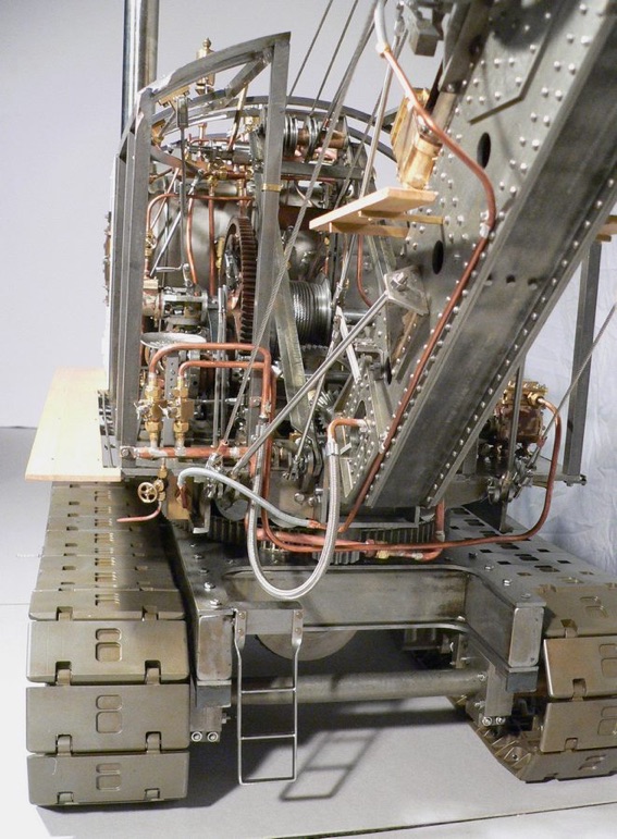
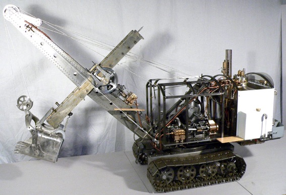
I built a cage to lift the revolving frame, which weighs 54kg.

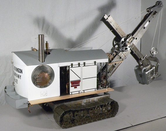
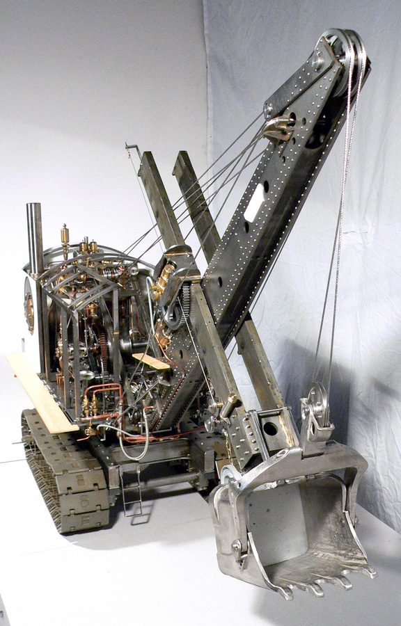
We begin with a series of views with the cab removed so you can see all the mechanisms:
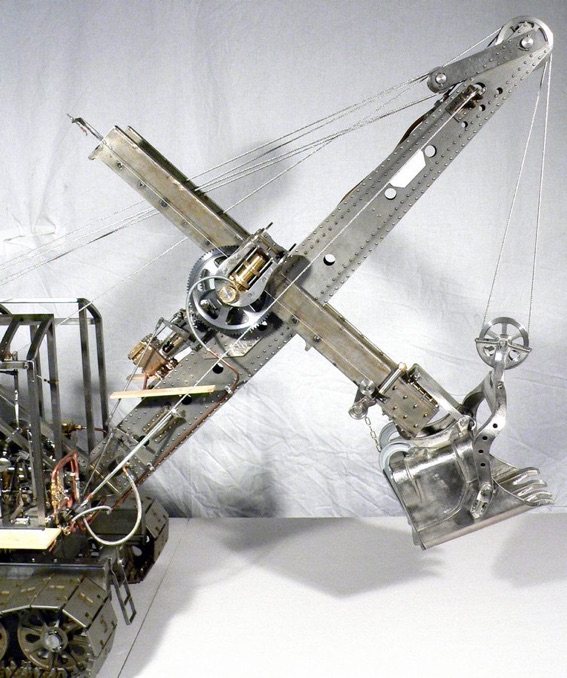


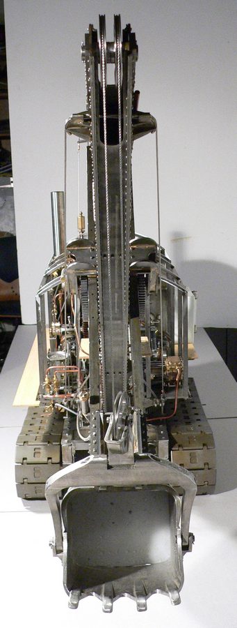
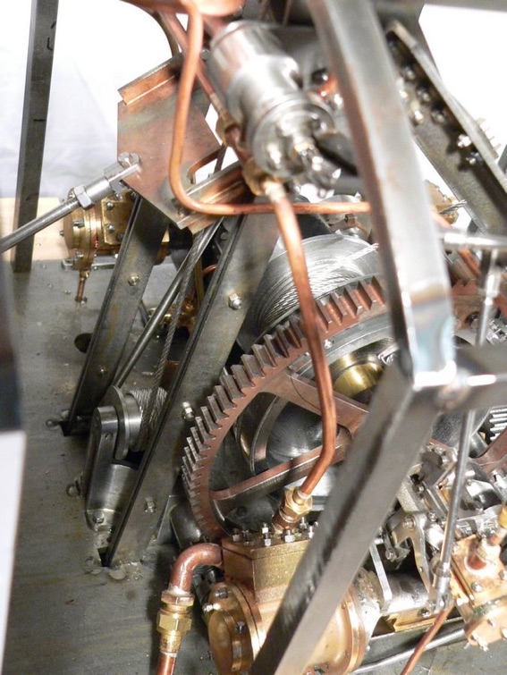
The second photo shows a front view where it can be noted that the axis of the pulley of the bucket is rotated to ensure that the two ends of the rope are spaced at the same pitch as the two upper pulleys:
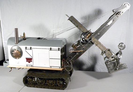
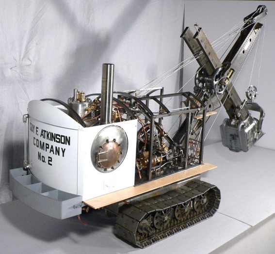
More views:

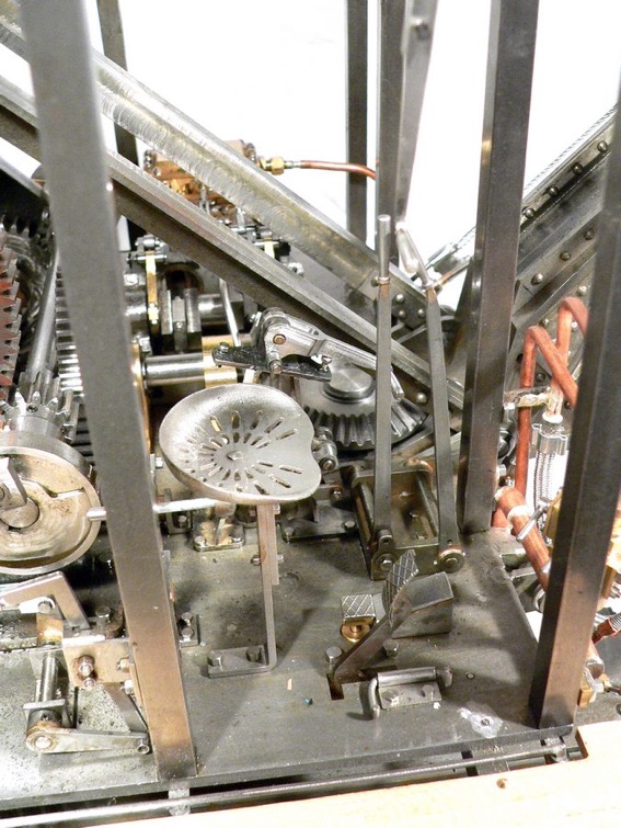

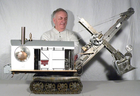
With reference to the last photo, the commands available to the operator sitting on the seat are:
A - Lever's Main Engine (pushing forward) and steam clutch (inserted with lever upright and off with lever moved laterally inward
B - reversing lever of the Main Engine
C - control lever of the Swinging Engine. With lever in the centre the engine is stopped, pushing forward the Revolving Frame rotates counterclockwise, while pulling back rotates clockwise
D - control lever of Thrusting Engine. With lever in the centre with the engine stopped, pushing forward the sliding arm Dipper Handle moves forward, while pulling back the arm moves backwards
E - lever for engaging the winch for lifting and lowering of the Boom, actuated by the Main Engine
F - Lever for the insertion of tracks traction, actuated by the Main Engine
G - Brake pedal of the winding drum of the rope for lifting of the bucket
H - Blocking of the brake pedal when it is in the braking position
I - Pedal to control opening Bucket door
L - Shut-off valve of Swinging Engine
M - Shut-off steam valve Thrusting Engine
Also behind the operator is a valve to shut off the steam to the clutch.
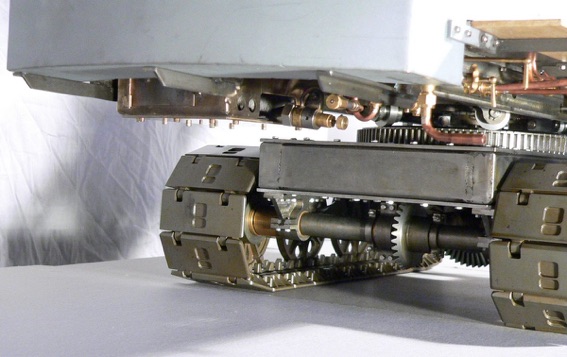
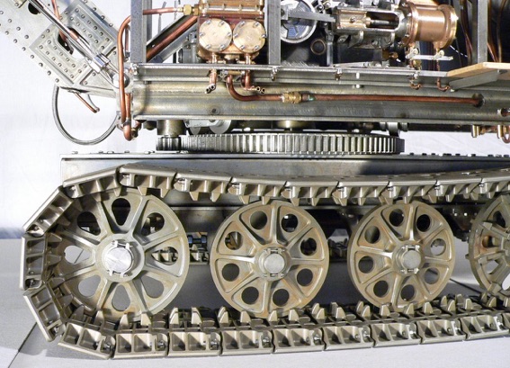
And now two photos of the transmission to the tracks and the combustion chamber with the burner.

MEWS IS SPONSORED BY - CHRONOS - PAULTHECAD.CO.UK - ECCENTRIC ENGINEERING - WARCO - BRISTOL EXHIBITION - HARROGATE EXHIBITION - MERIDIENNE EXHIBITIONS - CAMDEN MINIATURE STEAM - TRANSWAVE CONVERTERS - CHERRY’S MODEL ENGINES -
Model Engineering Website is edited by David Carpenter