DELAGE GRAND PRIX ENGINE PROJECT
Part seven by Mike Sayers

DELAGE GRAND PRIX ENGINE PROJECT
Part seven by Mike Sayers
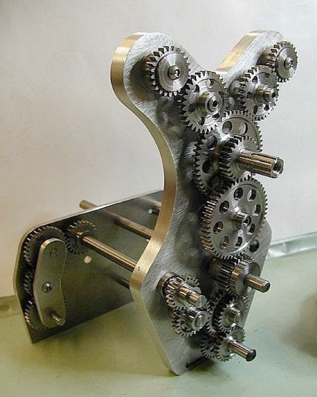
The gears are set up on jig plates to replicate installed positions. Each gear will be supported by a ball race on each side. No adjustment possible.
All the gears have been cut and mounted on the jig plates. This is basically a mockup used to check if the gears function correctly, before being installed in the model.

This is the model’s upper rear timing case, and three engaged gears have been installed. The ball race housings have been cut in, and the photo shows the timing case in its ‘rough form’. The timing case was eventually machined to its ‘final form’ as shown next:


The setup, shown in the photo, uses various odd bits of machinery found around the workshop, attached to my old Shaublin mill in horizontal mode. The hob cutter is similar to a worm in that it is spirally cut. This system automatically indexes.
If you want to cut a gear of a certain ratio you can. You just set the machine up for that gear ratio, start the machine and go away and have a cup of tea while the gear is cut.
The universal joint arm operating the worm onto the gear is there to turn the workpiece so that the hob will cut perfect teeth to the correct ratio.
The next photo shows the view on the work piece:


The cluster gears give a forward and reverse traverse.
Once all is set up, the process continually indexes the blank to the correct number of teeth as the cutter rotates, and cuts the teeth on auto traverse. Accurate depth of cut is set on the digital clock seen behind the cutter spindle.
It’s a nonstop, accurate and painless method.
It took two months to make the set up, though. To change the tooth number of the required gear, only one gear in the transfer chain needs to be changed, plus one cutter hob will produce gears of any number of teeth.

In a bevel gear, the width of the gap between the outer teeth is wider than the gap between the inner teeth. That presents a problem in how to cut them. They are usually cut by special milling machines.
However, Brown and Sharpe, during the First World War, devised a method of cutting bevels, not to produce precision bevels, but to produce decent serviceable bevel gears in large quantities all over the world.
Because the gap in the centre was less than the outside, they had to make a special cutter that would cut and finish the slot. To open up the slot towards the outside, one cut would be made down the middle. Then the workpiece would be rotated a few degrees, and the cutter moved slightly. Then a cut would be passed down the edge of one tooth, feathering into the inside and taking more from the outside. The same process was carried out on the other side of the slot along the edge of the adjacent tooth.
Once the bevel gear had been cut, the finishing process would be a fitter with a file ‘rounding off’. It should be noted however, that if the three pass method has been executed correctly, the ‘finishing process’ with a file will not be necessary.


It does not lose its place when the phone rings. Magic!
Part one here. Part two here. Part three here. Part four here. Part five Part six Part seven


Modelengineeringwebsite.com
the only free and the only weekly magazine for model engineers.
Editor: David Carpenter

