JOWITT MKII POPPET VALVE STEAM ENGINE
By Jason Ballamy - Part seven

JOWITT MKII POPPET VALVE STEAM ENGINE
By Jason Ballamy - Part seven

Now for the final parts - mostly simple turning jobs.
Click on drawings to download - for personal use only.
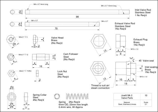
Inlet and Exhaust Rods
These are just lengths of 303 Stainless steel faced off to their respective lengths. Thread one end of each M4 x 4mm long for the valve head and the other M4 x 10mm long to allow adjustment of the cam follower.
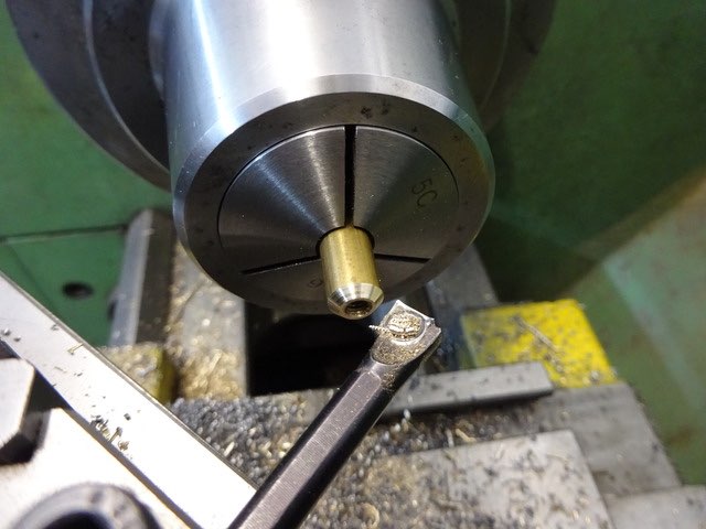
Valve Head
Drill and thread some 8mm dia brass M4 and then cut the 45deg seat, part off and repeat. I find it easier to use a boring bar on the rear of the work with the lathe running in reverse as its easier than reaching across the lathe to turn the top slide handle especially on a job like this where a good finish is needed if the valves are to seal. The heads should be screwed onto the valve rods with a small amount of thread lock.
Cam Followers
Face off two bits of 6mm hex steel 16mm long making sure the end that will run against the cam has a nice smooth finish. Turn down each end to 5.5mm diameter for a length of 4mm and then drill and tap M4 x 12mm deep.
Lock Nuts
These can be made from the same 6mm hex steel or you could use off-the shelf M4 nuts and reduce their thickness.
Spring Collars
Face some 8mm dia steel, drill 4mm through and then form the recess for the spring with a 6mm milling cutter, part off and repeat for the other 3 collars.
Springs
I have a couple of boxes of assorted springs which these came from, you want quite a soft spring approx 6mm OD, 25mm free length and 0.4mm wire thickness. Just enough to keep the valve closed but not offer too much resistance as the cam compresses them.
All the above parts for one side of the engine.
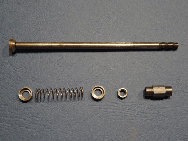
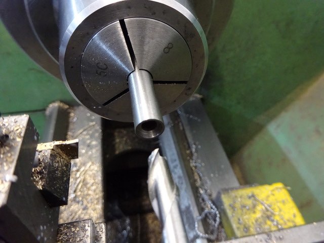
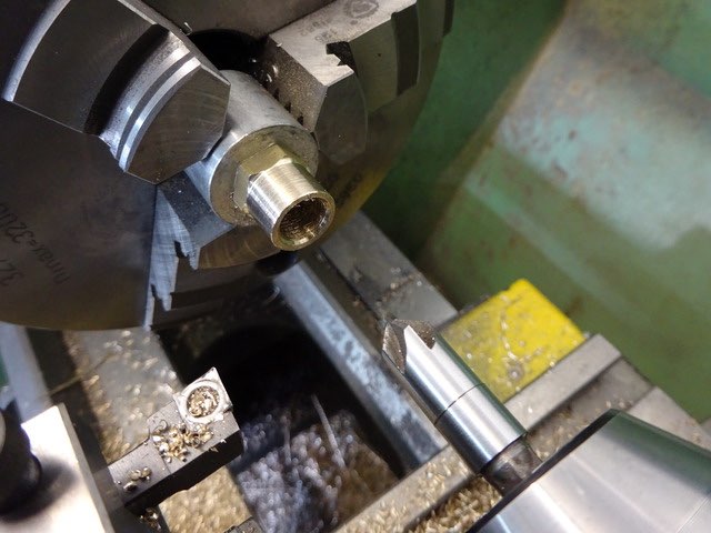
Exhaust Plug
Turn a spigot on the end of some 13mm or 1/2" brass rod and thread M10 x 1 or whatever thread you used on the cylinder, part off and then clean up the head with a light chamfer to the corners.
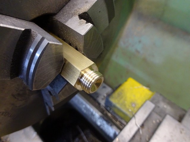
Inlet Seat
This is very similar to the Exhaust plug but should be parted off longer. Drill through 6mm dia and then open out and thread for your air/steam fitting, (1/8" BSP fits well). The bottom of this threaded hole should have a 45degree seat cut in a similar way to that of the exhaust seat in the cylinder.
Oil Cups
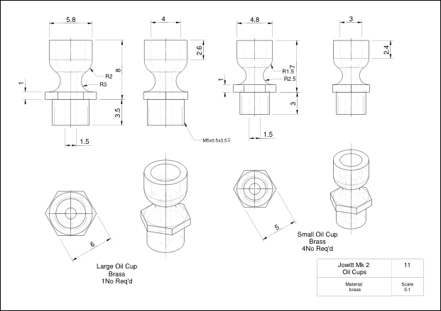
There are two sizes of oil cup but they can all be made in the same way. Start with a piece of hexagonal brass, face off and then turn and thread the spigot with a metric fine thread. At the same time drill the 1.5mm hole up through the middle then part off.
Now take a piece of scrap material and drill and thread so the embryo oil cup can be screwed into it. It worth spending a couple of mins doing a decent job as these holders will come in useful in the future, I have a range of sizes with female thread one end, male the other.
With a ball nosed milling cutter enlarge the 1.5mm hole to form the inside of the cup. Now you can either grind up a profile tool from a piece of HSS which can be used to turn down the top of the cup from hex to round and then fed in to create the neck as below. Or just use a round nosed tool the do the waist and use a file to round over the external angle blending the concave waist into the cup main diameter.

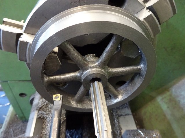
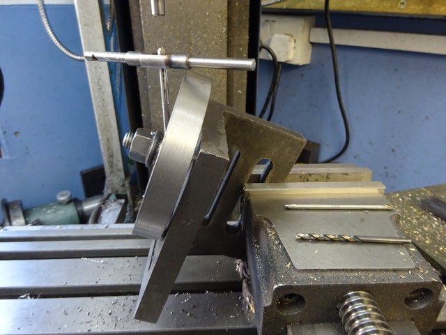
Flywheel
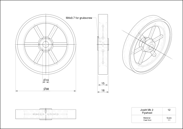
Depending where in the world you are located, nominal 4" or 100mm flywheel castings should be available. I went for a couple of Perseus ones from Reeves. The castings were quite nice so after a quick clean up with a file I was able to grip them by the inside of the rim using the 3-jaw chuck while the outer face and side were machined. The hub can then be faced, drilled to 9mm, bored to 9.8mm so the 10mm reamer has a true running hole to follow
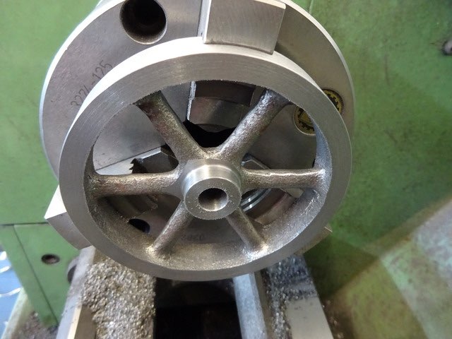
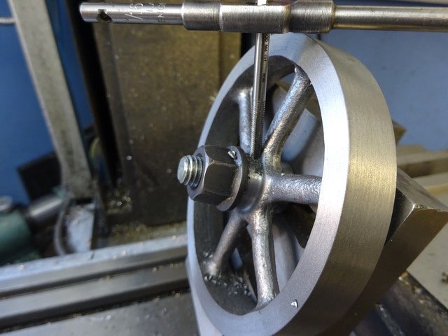
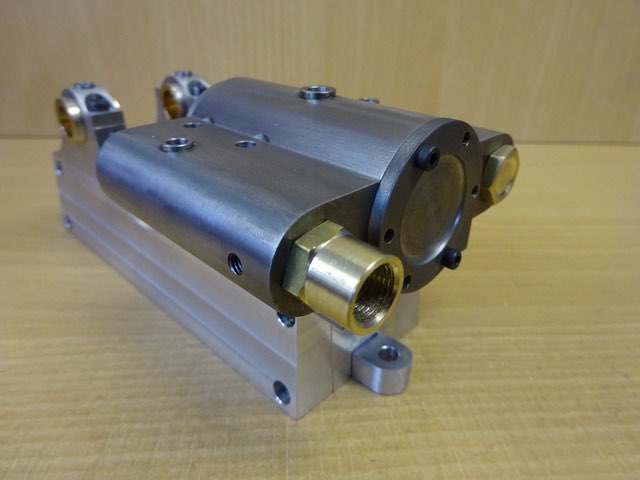
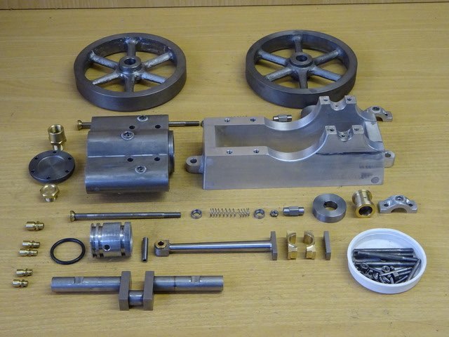
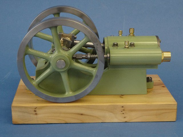
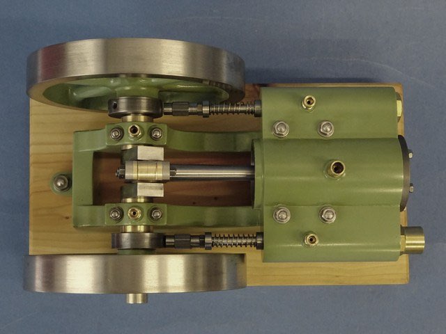
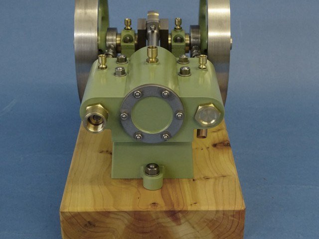
This is what I ended up with.
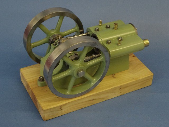
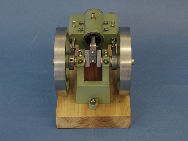
The finished engine. Not bad for 29 days from start to finish working a couple of evenings a week and part of the weekends.
Part one here Part two Part three Part four Part five Part six Part seven Part eight